Methods apparatus for generating shaped gradient fills

a gradient filling and gradient technology, applied in the field of image processing techniques, can solve the problem of not providing a means

Inactive Publication Date: 2005-03-22
ADOBE INC
View PDF3 Cites 41 Cited by
  • Summary
  • Abstract
  • Description
  • Claims
  • Application Information

AI Technical Summary

Benefits of technology

[0007]Particular implementations can include one or more of the following features. Applying the gradient can include, for each of a plurality of points located inside the outline, (i) identifying a color interpolation vector extending from the starting position through the point to the ending position, such that the color interpolation vector intersects the outline at one or more intersection points, and (ii) assigning a color for the point based on the point's position along the color interpolation vector. The selected region can have a regular or irregular shape. The shape of the selected region can be user-defined. The gradient can be a linear gradient or a radial gradient. The starting position can be a point located inside or outside of the outline. The starting position can be a line that intersects or does not intersect the outline. The starting position can be a start outline defining a starting shape. The starting position can be user-defined. The ending position can include at least a portion of the outline. For linear gradients, the gradient can be defined along a gradient axis extending from the starting position to the ending position, and the color interpolation vector can be parallel to the gradient axis. For radial gradients, the starting position can be a point and the color interpolation vector can extend radially from the starting position. Assigning a color for the point can include defining a gradient length for the color interpolation vector based on a distance between the starting position and at least one intersection point, defining a gradient interpolation parameter for the point by applying the defined gradient to the gradient length, and assigning a color for the point based on the gradient interpolation parameter. The gradient interpolation parameter for a point can represent the point's position along the color interpolation vector.
[0008]In general, in another aspect, the invention features computer-implemented methods and computer program apparatus implementing techniques for applying a radial gradient to shade a selected region in an image. The techniques include receiving an input selecting a region to be filled, the region having a shape defined by an outline, receiving an input defining a color transition to be applied between an origin in the image and the outline, and applying a radial gradient to shade the selected region by (i) identifying for each point within the outline a color interpolation vector extending from the origin through the point to the outline, such that the color interpolation vector intersects the outline at one or more intersection points, and (ii) assigning a color for the point based on the point's position along the color interpolation vector.
[0009]In general, in another aspect, the invention features computer-implemented methods and computer program apparatus implementing techniques for applying a linear gradient to shade a selected region in an image. The techniques include receiving an input selecting in an image a region to be filled, the region having a shape defined by an outline, receiving an input defining a gradient axis extending from a starting position in the image to a portion of the outline, and a color transition to be applied along the gradient axis, and applying a linear gradient to shade at least a portion of the object by (i) identifying for each point within the outline a color interpolation vector extending from the starting position through the point to the outline on a line parallel to the gradient axis, such that the color interpolation vector intersects the outline at one or more intersection points, and (ii) assigning a color for the point based on the point's position along the color interpolation vector.

Problems solved by technology

They do not, however, provide a means for using the geometry of the selected region or object to guide the application of gradient fills.

Method used


Image

  • Methods apparatus for generating shaped gradient fills
  • Methods apparatus for generating shaped gradient fills
  • Methods apparatus for generating shaped gradient fills

Examples


Embodiment Construction

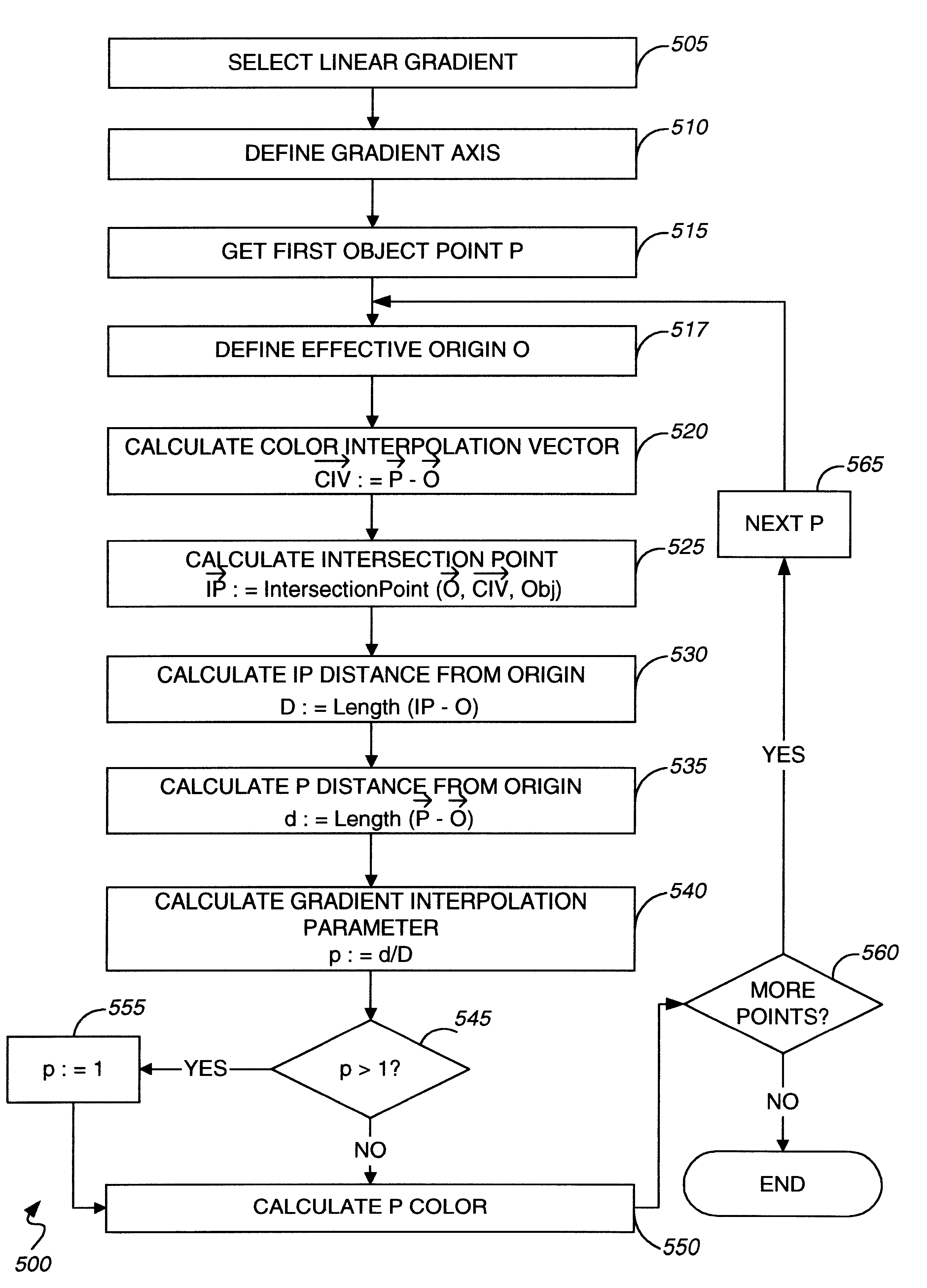
od of applying a linear shape gradient.

[0017]FIG. 6 depicts a number of objects filled using a linear shape gradient.

[0018]FIG. 7 illustrates a number of objects filled using a radial shape gradient.

[0019]FIG. 8 illustrates a number of objects filled using conventional and shaped radial gradients.

[0020]Like reference symbols in the various drawings indicate like elements.

DETAILED DESCRIPTION

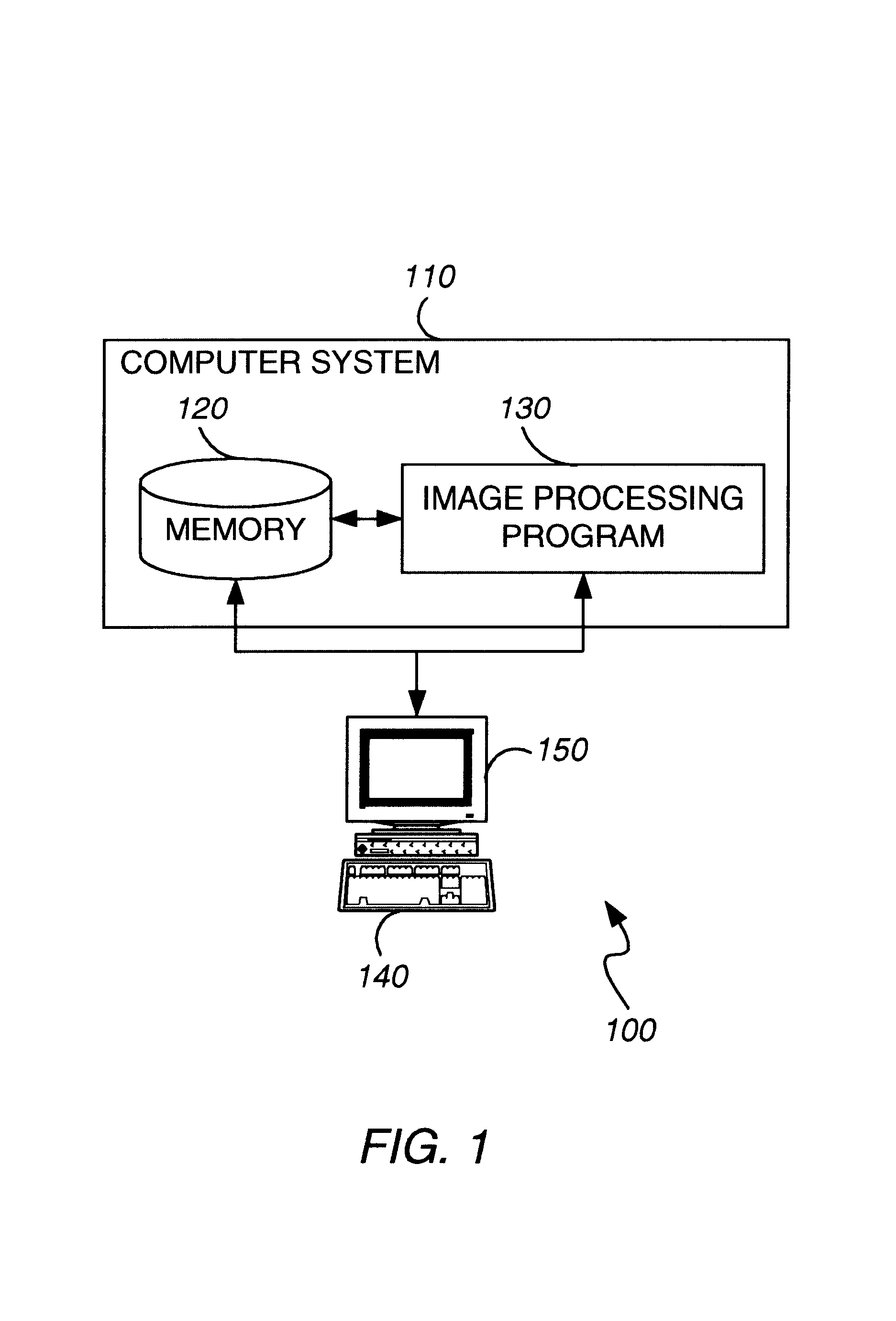
[0021]FIG. 1 illustrates an image processing system 100 that includes a general-purpose programmable digital computer system 110 of conventional construction, including a memory 120 and a processor for running an image processing program 130. Image processing system 100 also includes input devices 140, such as a keyboard, mouse or digitizing pen, and output devices such as a display monitor 150. Optionally, image processing system 100 also includes conventional communications hardware and software by which computer system 110 can be connected to other computer systems, such as over a network.

[002...


PUM


Abstract

Computer-implemented methods and computer program apparatus, for implementing techniques for shading selected regions of an image. These include receiving an input selecting a region to be filled, receiving an input defining a gradient specifying a color transition to be applied between a starting position and an ending position, and applying the gradient between the starting position and the ending position to assign, based on the shape of the selected region, a color for each of a plurality of points located inside an outline defining the region's shape. In preferred embodiments, the gradient is applied by identifying, for each point in the selected region, a color interpolation vector extending from the starting position through the point to the ending position and intersecting the outline at one or more intersection points, and assigning a color for the point based on its position along the color interpolation vector.

Description

BACKGROUND[0002]This invention relates to image processing techniques for smoothly shading objects and / or regions in an image. Conventional image processing computer applications provide a number of image processing techniques. Commercially available applications such as Photoshop® and Illustrator®, available from Adobe Systems Incorporated, of San Jose, Calif., implement gradient fill techniques for providing smooth color transitions along a vector from one color to another within a selected region or object in an image. Thus, a gradient fill can be considered a graduated blend or transition between two or more colors (or tints or shades of a color).[0003]Known gradient fill techniques can be divided into the following categories. First, in linear or axial gradients color varies between specified boundary colors along a line between starting and ending coordinates (called the gradient axis), forming a series of isochromal lines (lines of the same color in the transition) extending ...

Claims


Application Information

Patent Timeline
Patent Type & Authority Patents(United States)
IPC IPC(8): G06K9/00G06T11/20G06T11/00
CPCG06T11/40
Inventor GUPTA, NIRAJ
Owner ADOBE INC
Why Eureka
Try Eureka