Computerized stitching including embroidering

a technology of embroidering and computerized stitching, which is applied in the field of stitching machines, can solve the problems of increasing the amount of backing material required, increasing the cost of backing material, and creating more tension than is required in typical systems, so as to reduce the need for backing material, reduce the need for thread breaks, and reduce the effect of thread tension

Inactive Publication Date: 2005-03-29
MELCO INT
View PDF13 Cites 10 Cited by
  • Summary
  • Abstract
  • Description
  • Claims
  • Application Information

AI Technical Summary

Benefits of technology

The present invention is an apparatus that can stitch with less tension, reducing the likelihood of thread breaks and the need for additional materials. It includes a thread break monitor that doesn't need to be placed in the lower arm of the apparatus. The invention also uses an active thread feeder to calculate the amount of thread needed and adjust its feeding accordingly based on the tension in the thread.

Problems solved by technology

The technical problem addressed in this patent text is the need for an improved stitching machine that can easily adjust the presser foot to properly move the garment without causing damage or discomfort to the operator. Current machines require the operator to manually adjust the presser foot to ensure it does not hit the hoop or cause damage to the garment. The invention aims to solve this problem by allowing for easy adjustment of the presser foot without the need for the operator to physically pull down the needle. This would be advantageous in terms of cost and labor efficiency. The machine should also be able to visually verify the needle will not hit the hoop without having to adjust the needle case.

Method used


Image

  • Computerized stitching including embroidering
  • Computerized stitching including embroidering
  • Computerized stitching including embroidering

Examples


Embodiment Construction

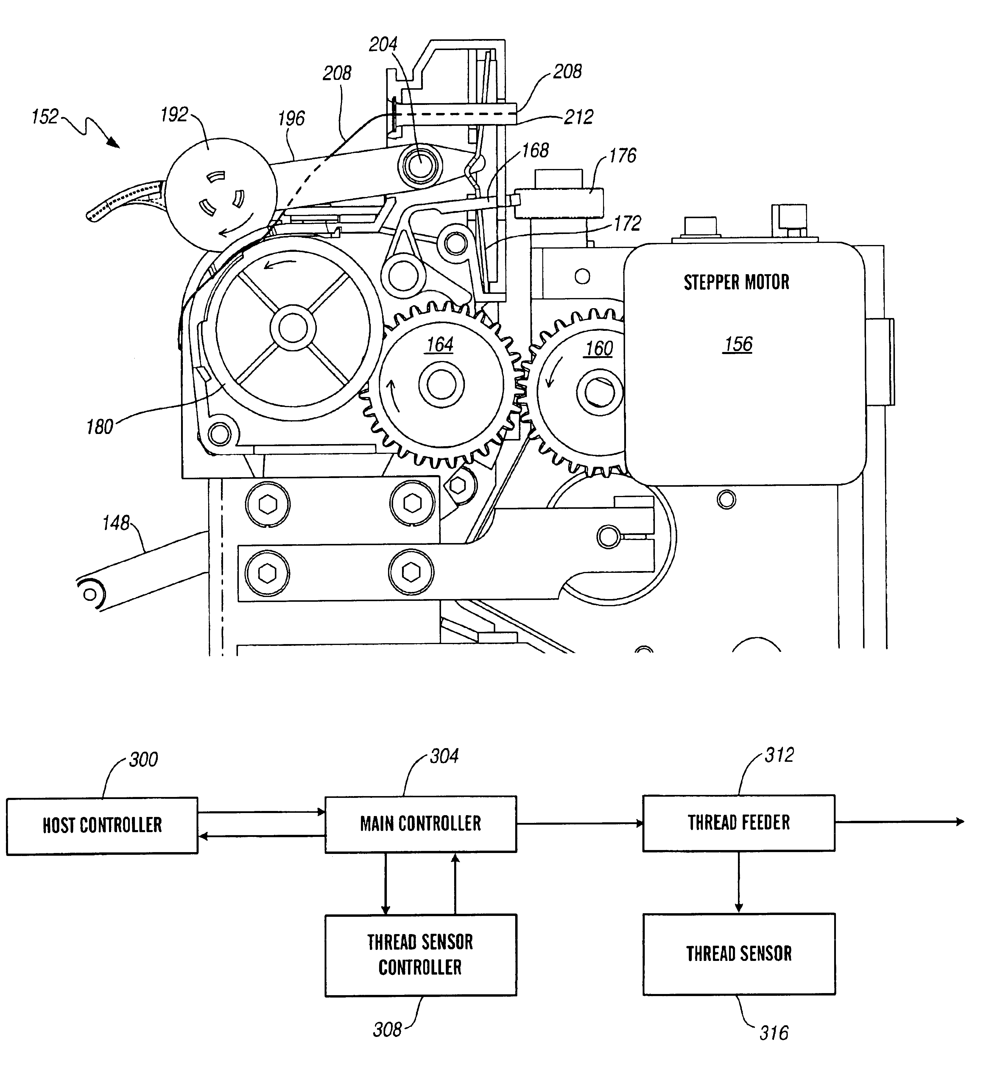
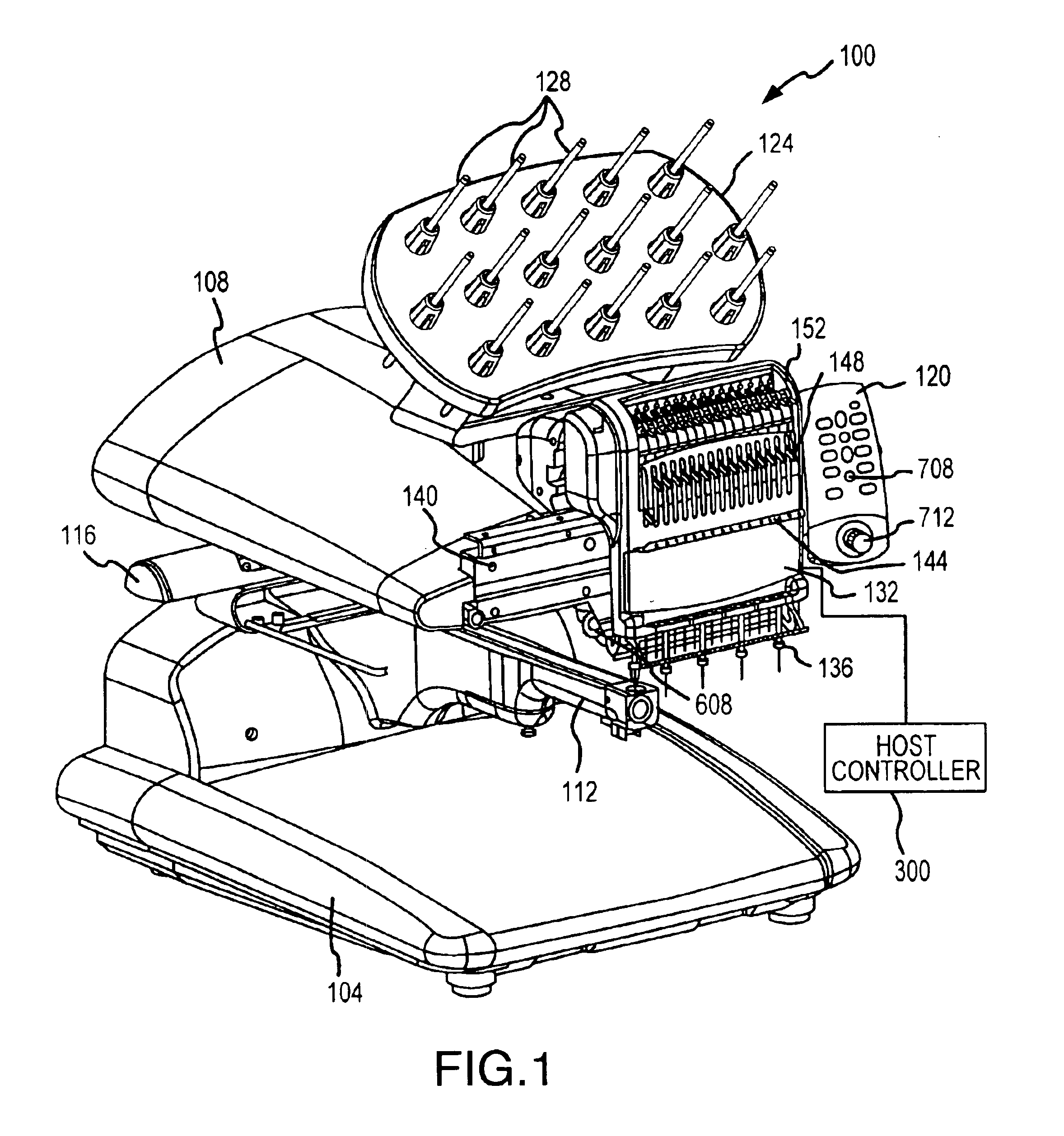
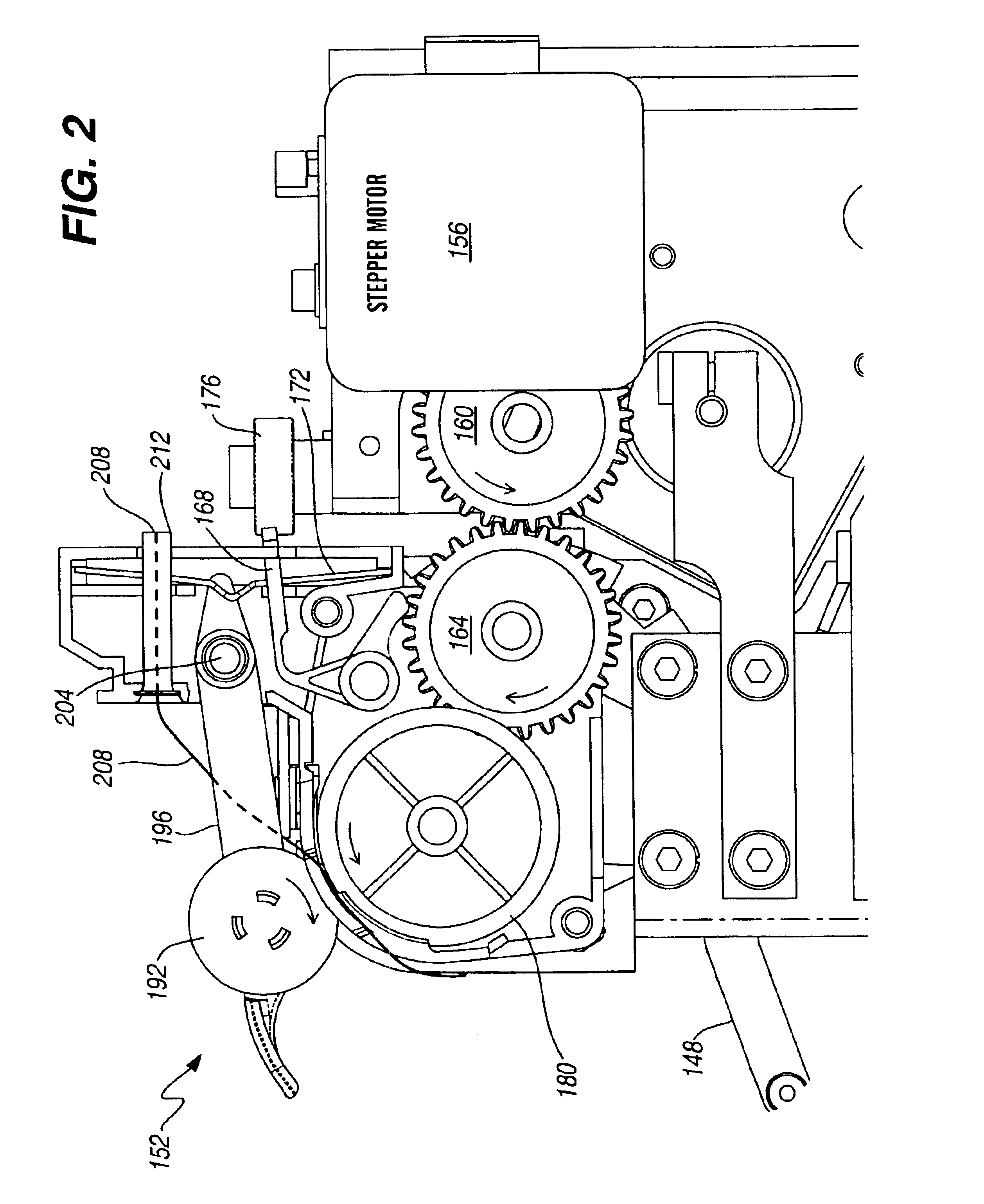
Referring to FIG. 1, a front perspective representation of one embodiment of the invention is now described. The embroidery machine 100 has a base assembly 104, an upper arm assembly 108 mounted to the base assembly 104, a lower arm assembly 112 mounted to the base assembly 104, and an X-Y drive assembly 116 mounted to the base assembly 104. Within the base assembly 104 is a main controller (not shown), which receives patterns to be stitched into a garment from a host controller 300, receives manual commands from a user interface 120, and controls stitching operations. The host controller 300 is a computer which allows a user to input, select, and download design patterns to the main controller. The host controller 300 may be any suitable computer for a user interface, including a Windows based PC, an Apple Macintosh type computer, a UNIX based computer, or any other similar computer capable of providing a user interface and input, selection, and download capabilities.

Mounted to the...


PUM


Abstract

A stitching apparatus is disclosed which has at least one active thread feeder and is operable to adjust stitching operation based on the condition of a thread being stitched. The active thread feeder is operable to feed thread from a spool to a needle assembly, where the thread is stitched into fabric. The stitching apparatus includes at least one thread sensor. The thread sensor outputs information related to thread tension, which is received at a control which includes a first controller, and the first controller is used for controlling the thread. The control can calculate a thread feed length, and activate the active thread feeder to feed the appropriate amount of thread to the needle assembly. The control can use information from the thread sensor to adjust thread tension by adjusting the active thread feeder. The control can also detect a break in the thread, or a break in an underthread which is located in a lower arm assembly and is used to lock stitches. The thread sensor is located more adjacent to the thread than to the underthread.

Description


Claims


Application Information

Patent Timeline
Owner MELCO INT
Why Eureka
Try Eureka