Valve flange connection

a technology for valve flanges and connections, applied in valve housings, functional valve types, transportation and packaging, etc., to achieve the effect of greater product economy of scale in manufacturing

Inactive Publication Date: 2005-03-29
VAL MATIC VALVE & MFG
View PDF6 Cites 5 Cited by
  • Summary
  • Abstract
  • Description
  • Claims
  • Application Information

AI Technical Summary

Benefits of technology

In an embodiment, object of the present invention is to provide a unique flange configuration for an in-line mounted valve that can be used with multiple bolt patterns while simultaneously centering the valve within the connecting bolts. The novel arrangement of tabs and intervening portions on the exterior of the body, as well as arcuate shapes, allows the inventive flange of the valve to be used with both U.S. customary bolt patterns and ISO (European) metric bolt patterns. Further, the shape of the flange can be arranged to allow for as-cast shapes, providing further economy. Configurations embodying the principles of the present invention can be provided which require no machining or special casting methods, such as the use of loose molding cores.
With the capability for universal mounting, the manufacturer can benefit from a greater product economy of scale in manufacturing. The members of the valve supply chain benefit from a universal mounting arrangement because they are able to stock fewer valve types and configurations. Since valves are stocked in many sizes, materials and types, a universal mounting arrangement over a range of pipe sizes can provide significant savings.
The tabs and intervening flange portions can be arranged to center the valve for different types of bolt patterns and still provide for correct rotational orientation of the valve. As described above, certain check valves require that the valve be installed with an exact orientation (i.e., the valve pin must be exactly vertical for proper operation). The correct orientation of the stem allows the closure members to rotate without binding and provide for a consistent valve operation in terms of set point or closing characteristics.
Finally, the valve body and flange can be designed as a casting which can be produced without the need for cores or other expensive casting methods. All points along the outside shape of the valve body and flange are capable of being pulled away from a parting line without crossing over any other points. This way a casting pattern can be pressed into a sand mold and lifted out to make the exact impression in the sand.

Problems solved by technology

However, there are actually different standards for bolt circles, particularly differences between U.S. bolt patterns and ISO (European) metric bolt patterns.

Method used


Image

  • Valve flange connection
  • Valve flange connection
  • Valve flange connection

Examples


Embodiment Construction

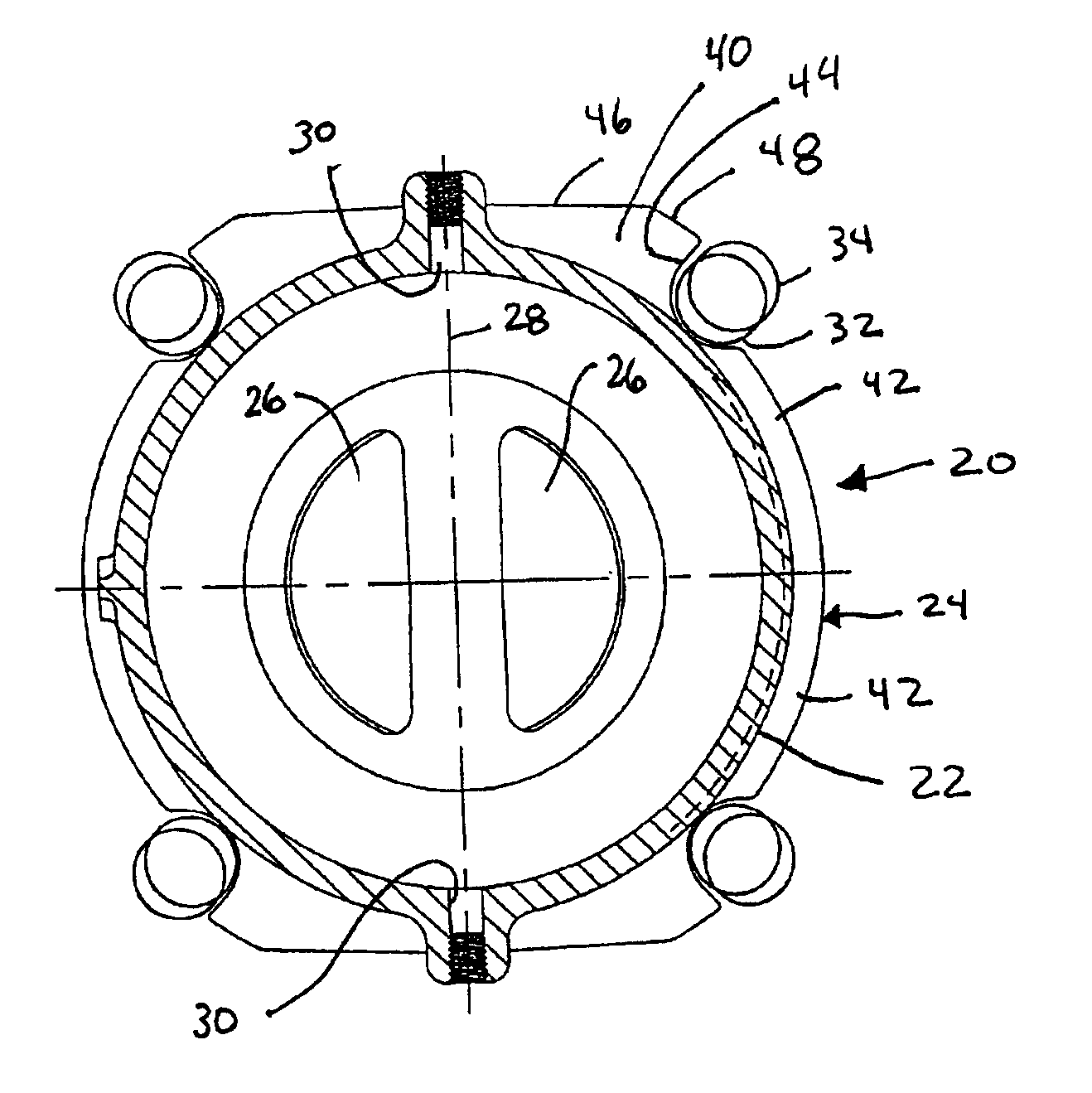
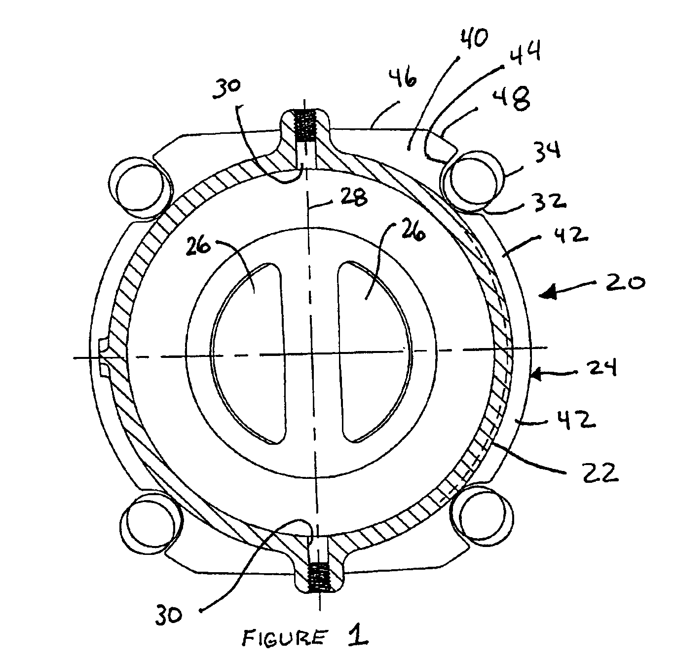
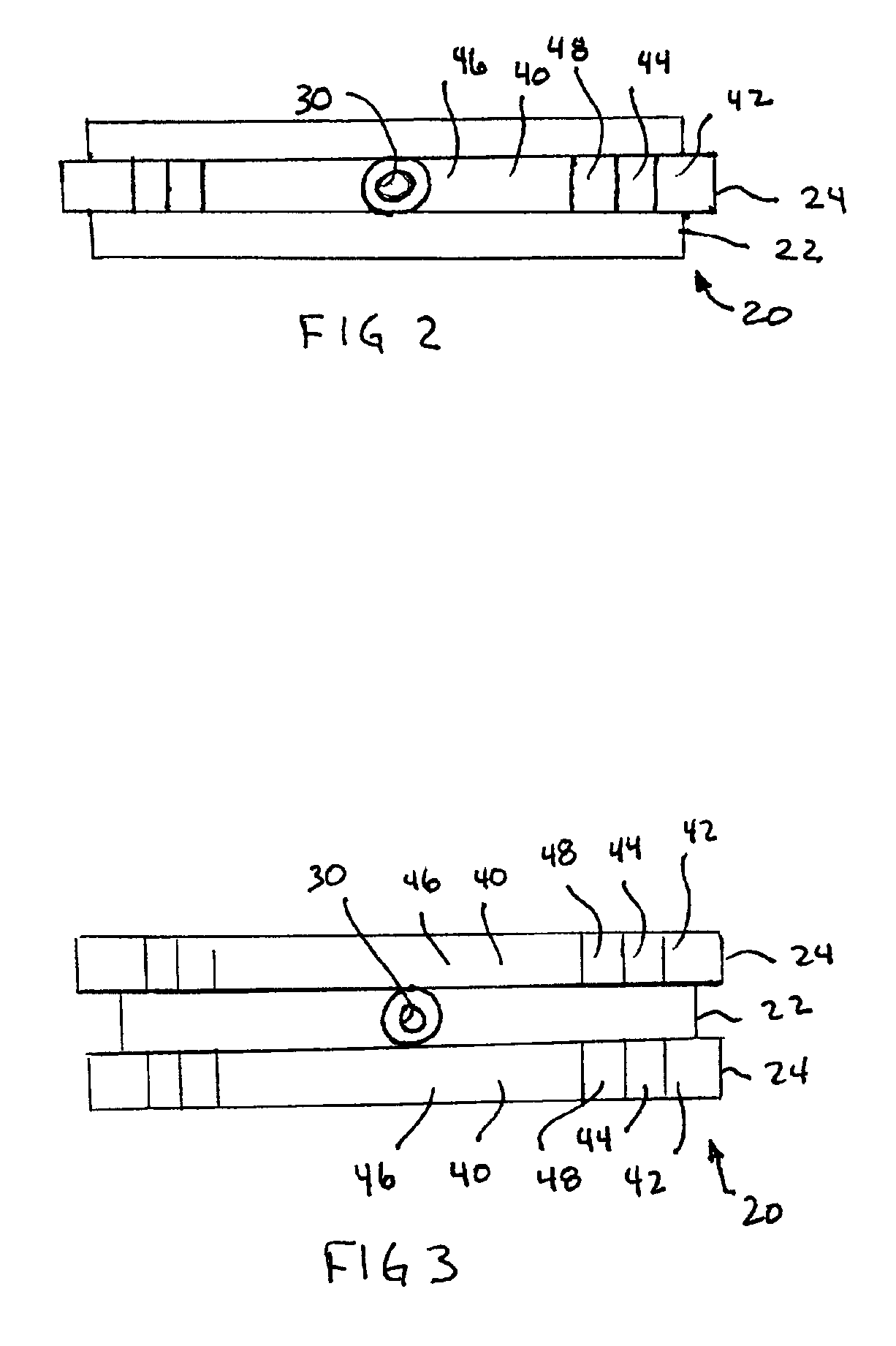
The present invention relates to a flange and in particular a flange for use with a valve body to be inserted in a pipeline. Many different types of valves can utilize the particular flange embodying the principles of the present invention, however a particular embodiment is illustrated in a check valve and in particular a wafer style check valve.

In FIG. 1 a wafer style check valve is shown generally at 20 and includes a generally cylindrical valve body 22 with a flange 24 having a peripheral edge extending radially outwardly from the valve body. The check valve has a pair of D-shaped disks 26 which rotate about a vertical axis 28, such as on a hinge pin which can be seated in appropriate journal openings 30 in the valve body 22. It is typical for in-line valves to be secured to the pipeline by being sandwiched between two flanged ends of a pipe with the flanged ends of the pipe being secured together by threaded bolts. In some valves, such as the check valve illustrated, it is impo...


PUM


Abstract

A flange is provided for a valve which extends in a radial direction outwardly from the valve and has a peripheral edge. The peripheral edge is comprised of a series of outer surfaces positioned at or beyond a first radial distance from a center point of the valve, and may be in the form of tabs, and an alternating series of inner surfaces positioned at or within a second radial distance from the valve or flange center point, as intervening portions. At least one of the outer surfaces and inner surfaces may be sized and arranged to supportingly engage a plurality of series of connecting bolts which extend perpendicular to the radial direction, wherein the plurality of series of connecting bolts are arranged on bolt circles of different diameters relative to the valve.

Description

BACKGROUND OF THE INVENTIONThe present invention relates to a configuration for a flange and more particularly for a flange used on a valve, such as a check valve located in a pipe run.Valves arranged in a pipe run, such as check valves, are well known. A particular type of check valve which is utilized in such an orientation is what is referred to as a wafer style check valve or dual disk check valve such as those disclosed in U.S. Pat. Nos. 4,079,751; 4,257,451; 5,301,709 and 5,711,343.In these check valves, an outer cylindrical valve body typically mates at each end with a pipe run wherein the ends of the adjoining pipes are provided with flanges and the check valve is captured between the pipe flanges such as shown in FIGS. 2 and 3 of U.S. Pat. No. 4,079,751.Typically the valve body is also provided with one or more flanges which are sized to engage the sides of the bolts extending between the pipe flanges. The bolts are arranged in a bolt circle and thus the radial inside surfa...

Claims


Application Information

Patent Timeline
Patent Type & Authority Patents(United States)
IPC IPC(8): F16K27/02F16K15/03F16K15/02
CPCF16K15/03F16L23/006F16L23/003F16K27/0209Y10T137/7839F16K15/035F16K15/038
Inventor O'SHEA, TIMOTHY MATTHEW
Owner VAL MATIC VALVE & MFG
Why Eureka
Try Eureka