
Trailing arm suspension anti-roll bar

Inactive Publication Date: 2005-03-29
ARVINMERITOR TECH
View PDF8 Cites 16 Cited by
  • Summary
  • Abstract
  • Description
  • Claims
  • Application Information

AI Technical Summary

Benefits of technology

Accordingly, the above invention provides an anti-roll bar for a heavy duty trailing arm suspension system that is serviceable without adversely affecting the ground clearance of the suspension system.

Problems solved by technology

Supporting an anti-roll bar by a frame for heavy duty vehicle applications is not practical since the suspension components may be spaced a significant distance from the frame so that a portion of the frame may not be located sufficiently close to the anti-roll bar.
Accordingly, it is difficult to isolate any one bushing to optimize the roll characteristics.

Method used


Image

  • Trailing arm suspension anti-roll bar
  • Trailing arm suspension anti-roll bar
  • Trailing arm suspension anti-roll bar

Examples


Embodiment Construction

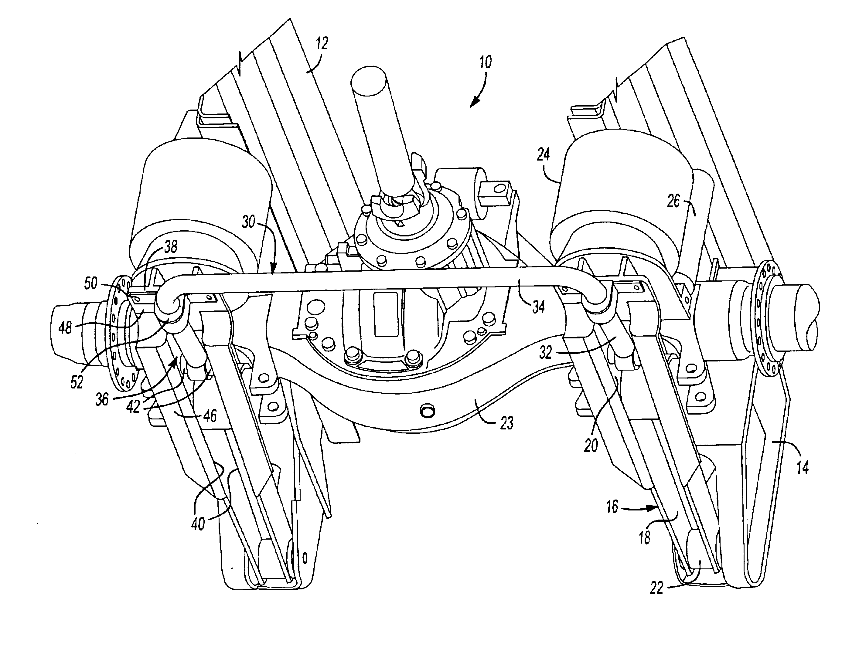
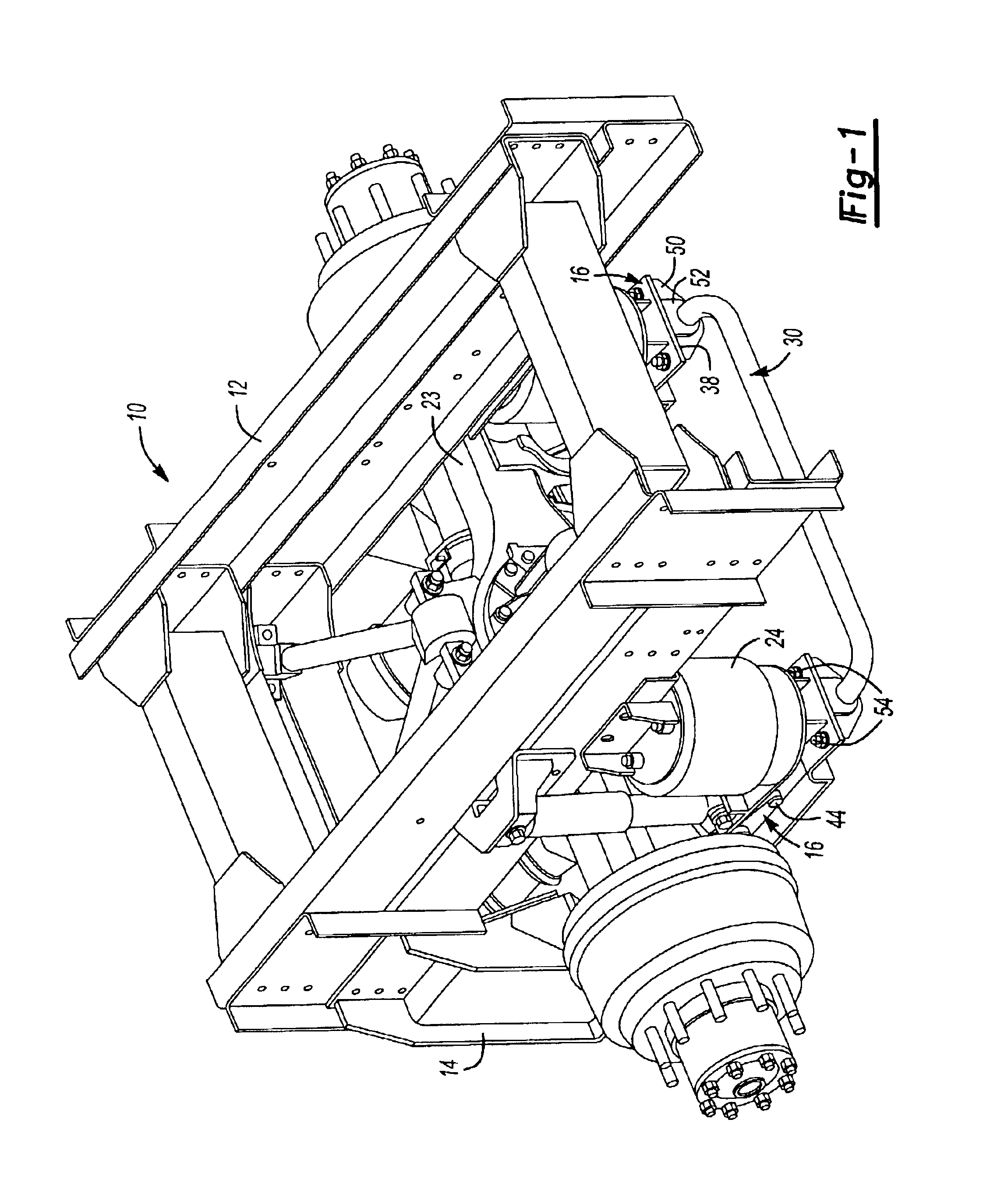
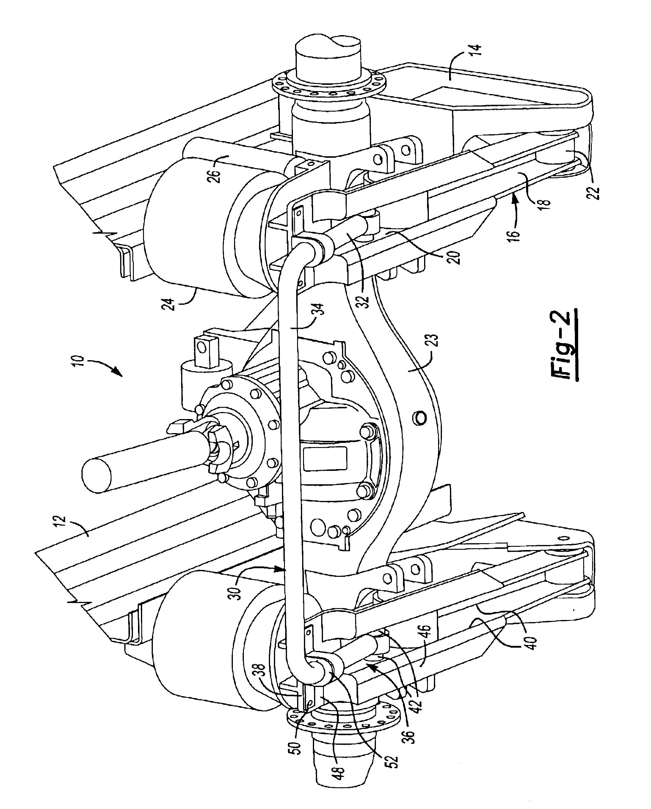
A heavy-duty suspension system is shown at 10 in FIGS. 1 and 2. The suspension 10 includes a frame 12 that may include any number of brackets 14 and other structural support members. The suspension 10 shown is suitable for use in such heavy-duty applications such as motor homes. The suspension 10 includes trailing arms 16 having forward portions 18 that are secured to the brackets 14 at first pivotal connections 22 by threaded fasteners. The trailing arms 16 extend from the forward portions 18 to rearward portions 20. The trailing arm is preferably formed from a thick metal forming and attachment features welded to the arm.

An axle 23, such as the drive axle shown, is pivotably supported on the trailing arms 16 by brackets and pins (not shown). For motor home applications a combustion engine may be arranged rearward of the suspension 10 to provide rotational drive to the drive axle 23. An air spring 24 and shock absorber 26 may be arranged between each of the trailing arms 16 and the...


PUM


Abstract

A trailing arm suspension is provided for use in a heavy-duty vehicle. The suspension includes a frame and a pair of spaced apart trailing arms that each include a forward portion pivotally supported by the frame. The trailing arms extend longitudinally from the forward portion to a rearward portion. An anti-roll bar includes opposing end portions and a central portion transverse to and extending between the end portions. The end portions are respectively arranged longitudinally along a portion of the trailing arms and are pivotally secured respectively to the trailing arms. The end portions may be secured to the trailing arms by threaded fasteners and further supported on the trailing arm by a bracket having a bushing. At least a portion of the end portion is received in a pocket or channel in the trailing arm so that the end portion does not extend below the trailing arm.

Description

BACKGROUND OF THE INVENTIONThis invention relates to a heavy-duty trailing arm suspension system, and more particularly, the invention relates to an anti-roll bar suitable for a heavy duty trailing arm suspension system.Suspension systems utilize anti-roll bars to stabilize the vehicle during a turning maneuver. One conventional type of anti-roll bar utilized on passenger vehicles includes ends that are secured to a suspension component such as a lower control arm. A central portion extends between the ends and is supported on the frame of the vehicle by brackets and bushings.As the control arms move during a turning maneuver, the anti-roll bar rotationally deflects and acts against the frame to provide vehicle stability. Supporting an anti-roll bar by a frame for heavy duty vehicle applications is not practical since the suspension components may be spaced a significant distance from the frame so that a portion of the frame may not be located sufficiently close to the anti-roll bar...

Claims


Application Information

Patent Timeline
IPC IPC(8): B60G11/27B60G1/00B60G11/26B60G9/02B60G21/055B60G21/00B60G9/00B60G7/00
CPCB60G9/00B60G21/0551B60G2204/1224B60G2200/343B60G2202/152B60G2200/315
Inventor REINECK, BENJAMIN R.
Owner ARVINMERITOR TECH
Learn More