Watch case

a watch case and case body technology, applied in the field of watches, can solve problems such as difficult implementation of solutions, and achieve the effects of simple, reliable, and low wear

Active Publication Date: 2005-03-29
ROLEX SA
View PDF6 Cites 23 Cited by
  • Summary
  • Abstract
  • Description
  • Claims
  • Application Information

AI Technical Summary

Benefits of technology

The object of the present invention is to provide a simple, reliable, long-life solution which therefore in practice experienc

Problems solved by technology

In this case, one of the problems is to contrive for the force necessary to overcome the return force exerted on the angular positioning markings to be more or les

Method used


Image

  • Watch case
  • Watch case
  • Watch case

Examples


first embodiment

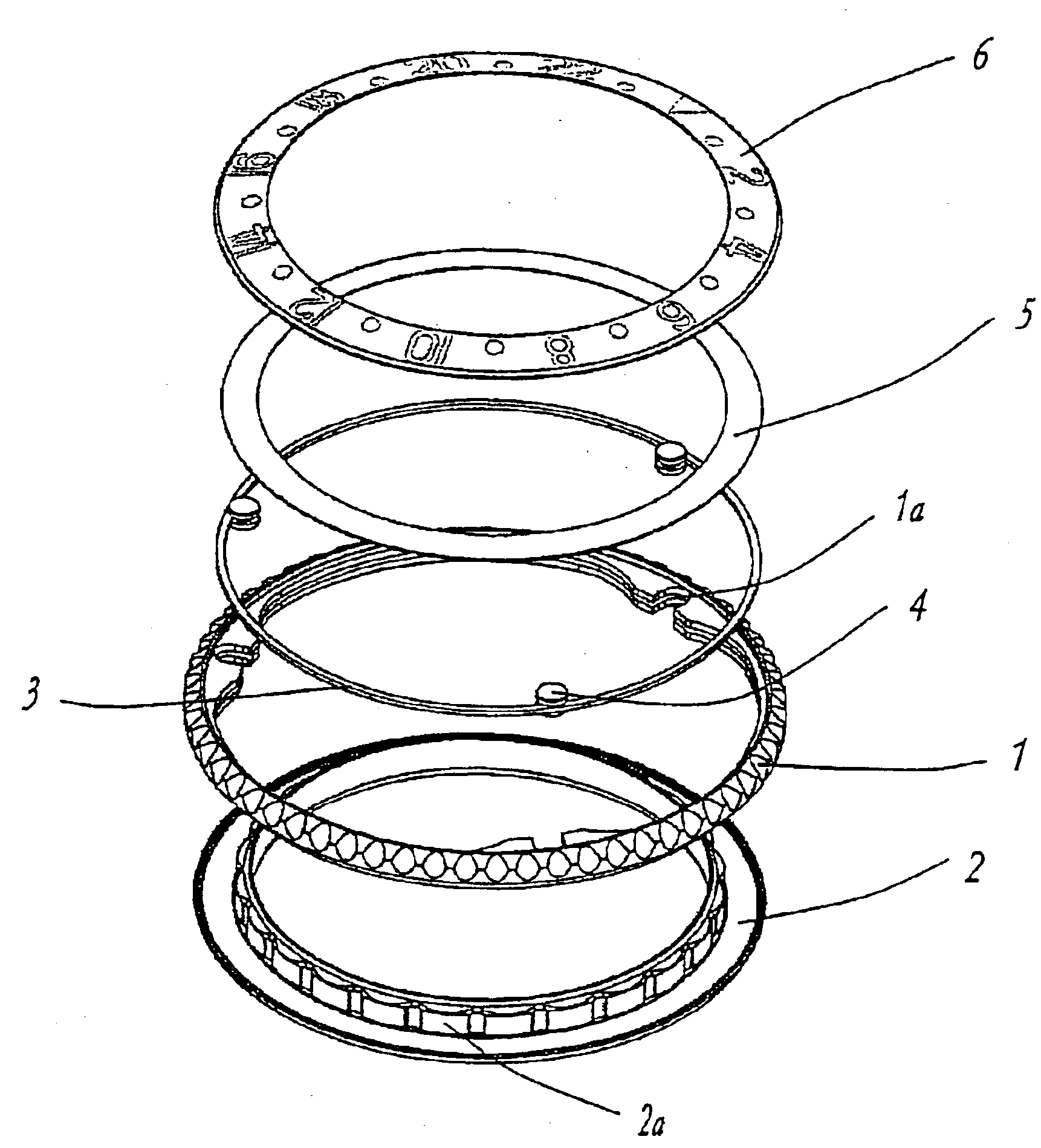
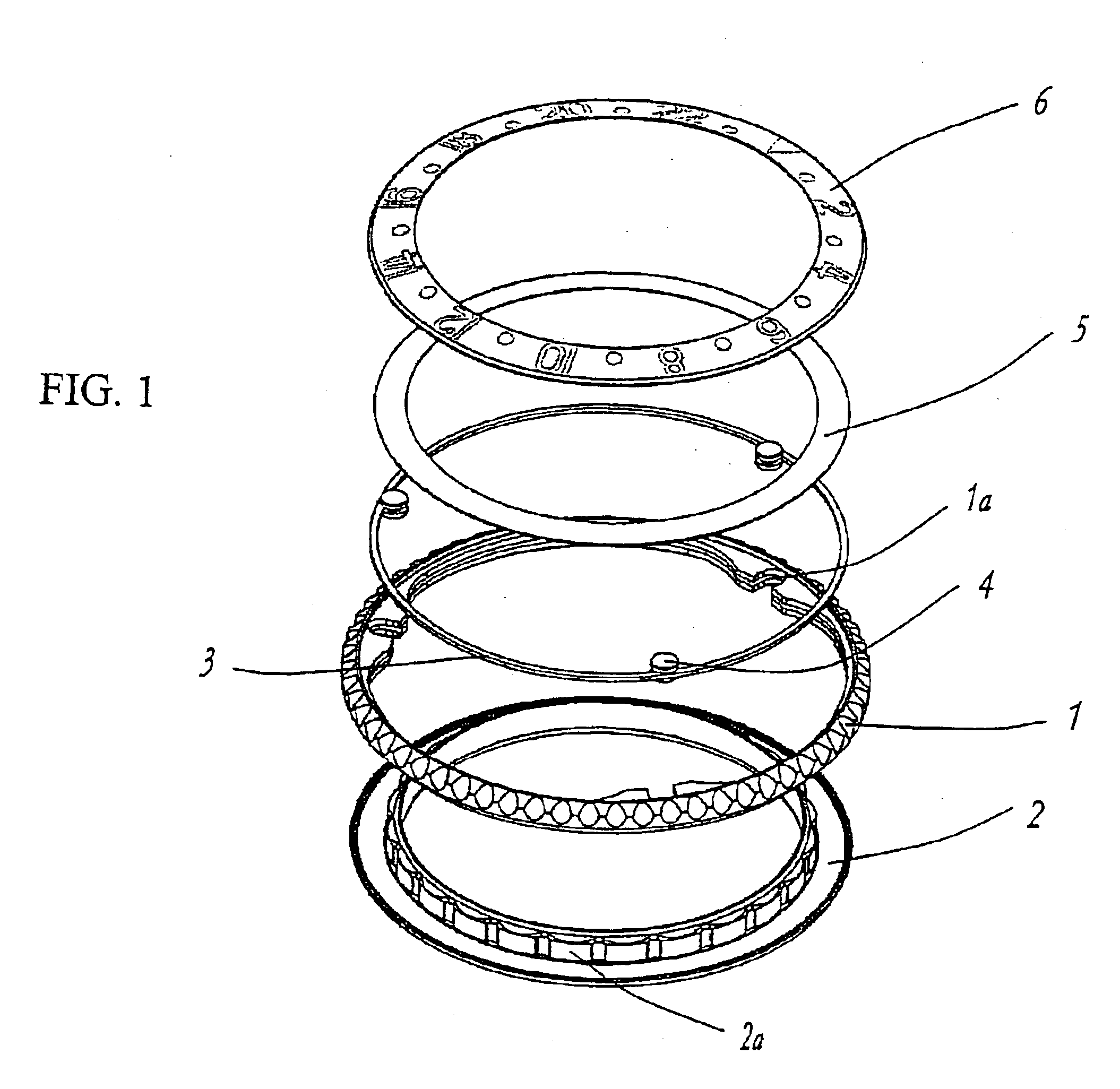
The rest of the rotary bezel mechanism is similar to the The position of the flat elastic annulus 5 which serves to press the two conical catches 1d, 2d against each other is changed in this embodiment, but its function remains the same.

third embodiment

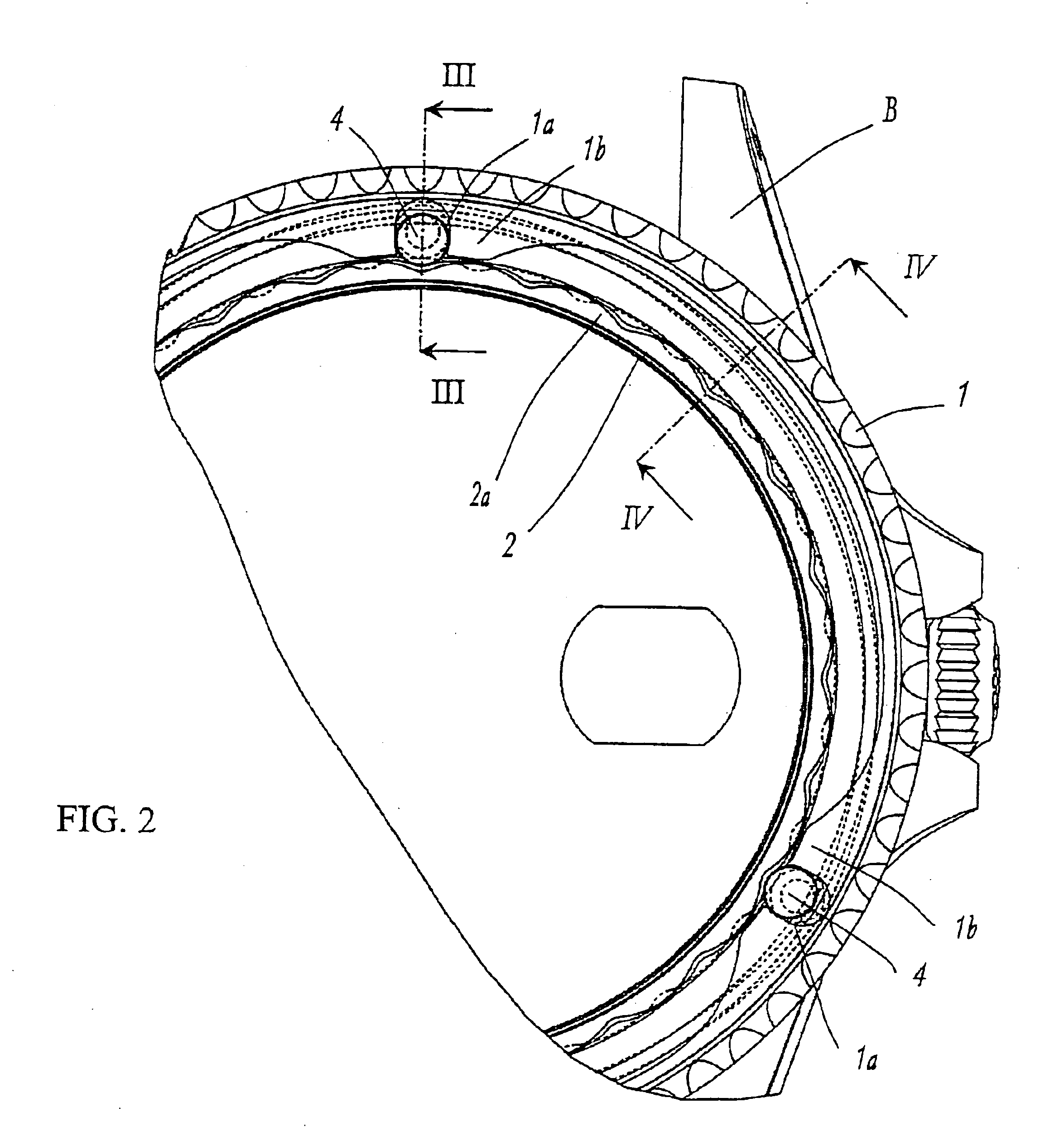
In the case of the third embodiment illustrated in FIGS. 8 to 11, the positions of the first and second angular markings are reversed by comparison with the previous embodiments, that is to say that it is the rotary bezel 21 which exhibits the first angular positioning markings 21a, while the closed-loop spring 23 has a fixed angular position with respect to a ring 22 secured to the case middle B corresponding to the ring 2 of the previous embodiments. The outline of the closed-loop spring 23 in plan view is cut out to form three projections 23a spaced 120° apart, to constitute the second angular positioning markings intended to engage simultaneously in three of the first angular positioning markings 21a the number of which is a multiple of these second angular positioning markings 23a.

Each projection 23a is associated with a radial protrusion 23b centered on the same radius as each protrusion 23a and directed toward the inside of the closed-loop spring 23. Each of these radial pro...


PUM


Abstract

A watch case comprising a rotary bezel, first and second angular positioning markings, one set secured to the bezel and the other set to the case middle and elastic means in the form of a closed-loop spring tending to place the positioning markings into engagement with one another. These markings are distributed with numbers of spacings one of which is a multiple of the other and the outlines of which extend in a plane parallel to that of the bezel. Guide means are engaged with the markings having the smallest number of spacings, in order simultaneously to exert on these markings radial pressures directed toward the other markings.

Description

CROSS REFERENCE TO RELATED APPLICATIONSThis application claims priority of European Application No. 02406123.6 filed Dec. 20, 2002, which is included in its entirety by reference made hereto.BACKGROUND OF THE INVENTION1. Field of the InventionThe present invention relates to a watch case comprising a case middle, a rotary bezel, first angular positioning markings secured to the case middle, second angular positioning markings secured to the rotary bezel and elastic means tending constantly to place said first and second positioning markings in engagement with one another.2. Description of the Related ArtA great many watch cases comprising a bezel mounted so that it can be turned are known. Such a bezel bears one or more indications that can be placed as desired in an angular position chosen from several determined angular positions, fixed by angular positioning markings kept in engagement by elastic return means. Some of these bezels can rotate in both directions. In this case, one ...

Claims


Application Information

Patent Timeline
IPC IPC(8): G04B19/28G04B19/00
CPCG04B19/283
Inventor HARTMANN, OLIVIERJAUSSI, ALBERTOMOILLE, DANIELPASSAQUIN, WILLIAM
Owner ROLEX SA
Why Eureka
Try Eureka