Medical diagnosis system having a medical diagnosis apparatus and a display to be observed by a patient

a medical diagnosis and display technology, applied in the field of medical diagnosis systems having medical diagnosis apparatuses and displays to be observed by patients, can solve the problems of less reliable examination results, patient cannot be explained nor directed of examination at the appropriate time, and complicated medical diagnosis techniques

Inactive Publication Date: 2005-03-29
TOSHIBA MEDICAL SYST CORP
View PDF9 Cites 12 Cited by
  • Summary
  • Abstract
  • Description
  • Claims
  • Application Information

AI Technical Summary

Problems solved by technology

Further, an operator of a medical diagnosis apparatus has been recently required more advanced skills and experiences of operations since such an apparatus has been recently highly sophisticated and medical diagnostic techniques have been more complicated.
This could make examination results less reliable.
Since, however, this entertainment is provided independently of the examination's progress, the patient can neither be explained nor directed of the examination at the appropriate timing.
Therefore, the patient has anxiety of when the examination will be finished, what will be d

Method used


Image

  • Medical diagnosis system having a medical diagnosis apparatus and a display to be observed by a patient
  • Medical diagnosis system having a medical diagnosis apparatus and a display to be observed by a patient
  • Medical diagnosis system having a medical diagnosis apparatus and a display to be observed by a patient

Examples


first embodiment

(First Embodiment)

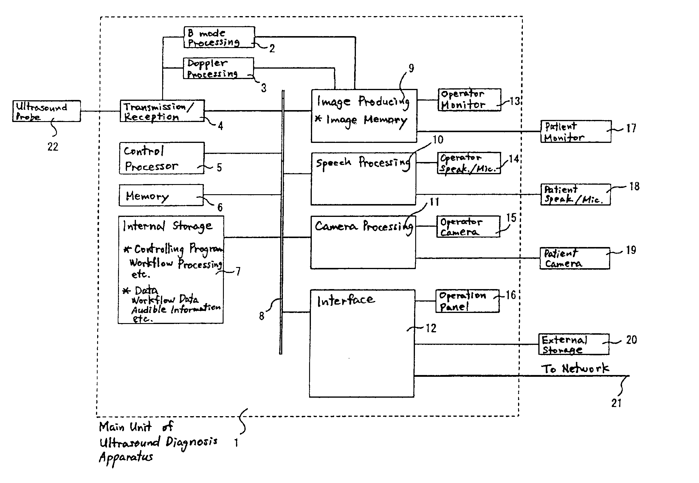
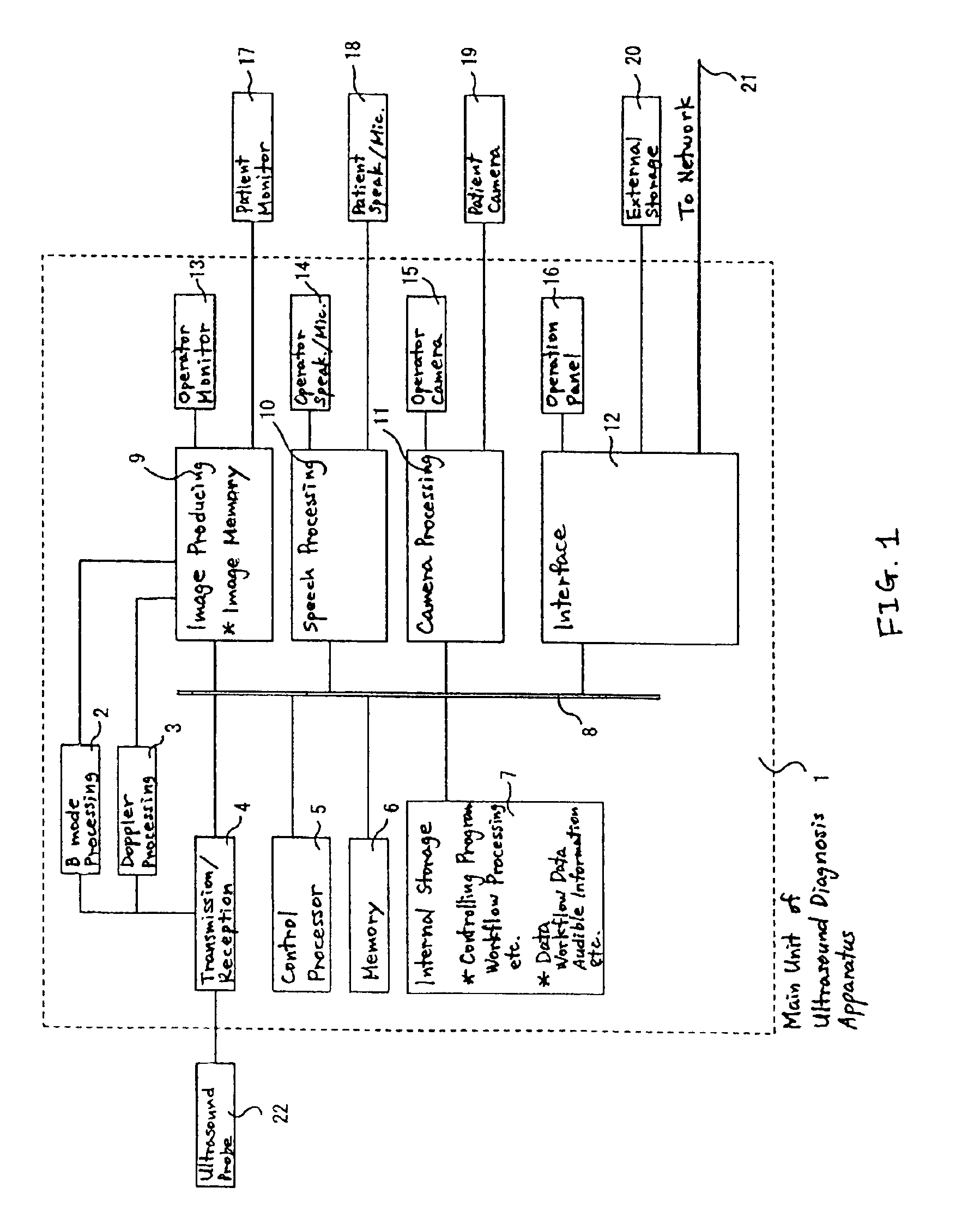
FIG. 1 is a block diagram showing an example ultrasound diagnosis system according to a first embodiment of the present invention. The ultrasound diagnosis apparatus comprises a main unit 1 and an ultrasound probe 22.

The main unit 1 of the ultrasound diagnosis apparatus comprises a B mode processing circuitry 2, a Doppler processing circuitry 3, a transmission / reception circuitry 4, a control processor 5, a memory 6, an internal storage device 7, bus 8, an image producing circuitry 9, a speech processing circuitry 10, a camera processing circuitry 11, an interface circuitry 12, an operator monitor 13, an operator speaker / microphone 14, an operator camera 15, and an operation panel 16.

The ultrasound probe 22 has an array of ultrasound vibration elements for converting between ultrasound signals and electric signals. The ultrasound probe 22 transmits and receives ultrasound signals to / from a patient. The transmission / reception circuitry 4 comprises a transmission cir...

second embodiment

(Second Embodiment)

The first embodiment was an example showing that the workflow processing and the production of image data and speech data for a patient were implemented in the main unit 1 of the ultrasound diagnosis apparatus. A second embodiment of the present invention is an example showing that the workflow processing and the production of image data and speech data for a patient is implemented in an independent personal computer (hereinafter referred to as PC).

FIG. 6(a) is a block diagram showing an ultrasound diagnosis system according to the second embodiment of the present invention. In this embodiment, the same components as those described in the first embodiment are omitted to avoid potential confusion.

The ultrasound diagnosis system comprises an ultrasound diagnosis apparatus 23, a workflow navigation PC 24, and an image display PC 25. These components are connected to one another in a mutually communicable form via a hospital LAN or communication lines 26 such as RS23...

third embodiment

(Third Embodiment)

The first embodiment was an example showing that the production of image data and speech data for a patient were implemented in the main unit 1 of the ultrasound diagnosis apparatus. A third embodiment of the present invention is an example showing that the production of image data and speech data for a patient can be implemented in an independent PC.

FIG. 6(b) is a block diagram showing an ultrasound diagnosis system according to the third embodiment of the present invention. In this embodiment, the same components as those described in the first embodiment are omitted.

The ultrasound diagnosis system in this embodiment comprises an ultrasound diagnosis apparatus 27 and the image display PC 25. These components are connected to each other in a mutually communicable form via the hospital LAN or the communication lines 26 such as RS232C. In addition, the ultrasound diagnosis apparatus 27 has an operator monitor 27a.

The workflow-processing program is executed in the u...


PUM


Abstract

A medical diagnosis system wherein a medical image is produced in a medical diagnosis apparatus, comprises a first storage device which stores an examination procedure for the medical diagnosis apparatus, a second storage device which stores supply information, a supply device which supplies the supply information stored in the second storage device, and a control processor which controls that the supply information is supplied in the supply device in accordance with the examination procedure stored in the first storage device.

Description

CROSS-REFERENCE TO RELATED APPLICATIONThis application is based upon and claims the benefit of priority from prior Japanese Patent Application No. P2001-208720, filed on Jul. 10, 2001, the entire content of which is incorporated herein by reference.FIELD OF THE INVENTIONThe present invention relates to a medical diagnosis system including an apparatus for medical diagnosis by, for example, ultrasound, X-ray, X-ray computed tomography (hereinafter referred to as CT), or magnetic resonance imaging (hereinafter referred to as MRI), and displays to be observed by a patient and a person to be examined by the apparatus (hereinafter referred to as a patient), and to a method of controlling the medical diagnosis system. The present invention further relates to such an apparatus for medical diagnosis and to a display to be observed by a patient both of which are used in the medical diagnosis system.BACKGROUND OF THE INVENTIONIt has been known that a medical diagnosis apparatus provides recon...

Claims


Application Information

Patent Timeline
IPC IPC(8): G06F19/00G16H30/20G16H50/20G16Z99/00
CPCG01S7/52098G06F19/3406G06F19/321G16H40/63G16H50/20G16H30/20G16Z99/00
Inventor KAMIYAMA, NAOHISASANO, AKIHIROOGASAWARA, YOICHI
Owner TOSHIBA MEDICAL SYST CORP
Why Eureka
Try Eureka