Reduced splattering of unpassivated laser fuses

Inactive Publication Date: 2005-03-29
INFINEON TECH AG +1
View PDF10 Cites 27 Cited by
  • Summary
  • Abstract
  • Description
  • Claims
  • Application Information

AI Technical Summary

Benefits of technology

In summary, the present invention provides a measure of protection against the splattered fuse material of unpassivated laser fuses that may damage the integrity of neighboring fuses. The present invention does not require any additional processing steps. Rather, the specific layout of the metal layer that forms the fusable link is modified. The present invention provides the protection against the splattered material through the use of metal lines that run on both sides of the fusable link. The metal lines may be connected to a via that establishes an electrical connection to other circuitry, but the length and other physical characteristics (such as thickness and width) of the metal lines should be set to ensure that electrical connection between the vias connected to the blown fusable link is not possible after the fuse blowing process takes place. The metal lines serve as a mechanical barrier against splattering molten metal that is generated during the fuse blowing process.
The present invention provides a number of advantages. For example, use of a preferred embodiment of the present invention affords protection for fuses adjacent

Problems solved by technology

However, depending on the price for which the integrated circuit sells, certain functions may be disabled.
Typically, when an integrated circuit undergoes testing to verify its operation, faulty portions of the integrated circuit are marked (or stored) by the test equipment.
The splattered fuse material may then cause adjacent fuses to behave incorrectly, i.e., cause a previously blown fuse to behave like an unblown fuse or adjacent blown fuses to become short circuited together.
If this happens, the integrated circuit does not behave properly.
Unpassivated laser fuses do not have the passivation layer and are open to damage from an unfriendly environment.
On the one hand, the passivation layer makes it more difficult to blow the laser fuses.
In integrated circuits that are built up by using materials with low mechanica

Method used


Image

  • Reduced splattering of unpassivated laser fuses
  • Reduced splattering of unpassivated laser fuses
  • Reduced splattering of unpassivated laser fuses

Examples


Example

The making and use of the various embodiments are discussed below in detail. However, it should be appreciated that the present invention provides many applicable inventive concepts, which can be embodied in a wide variety of specific contexts. The specific embodiments discussed are merely illustrative of specific ways to make and use the invention and do not limit the scope of the invention.

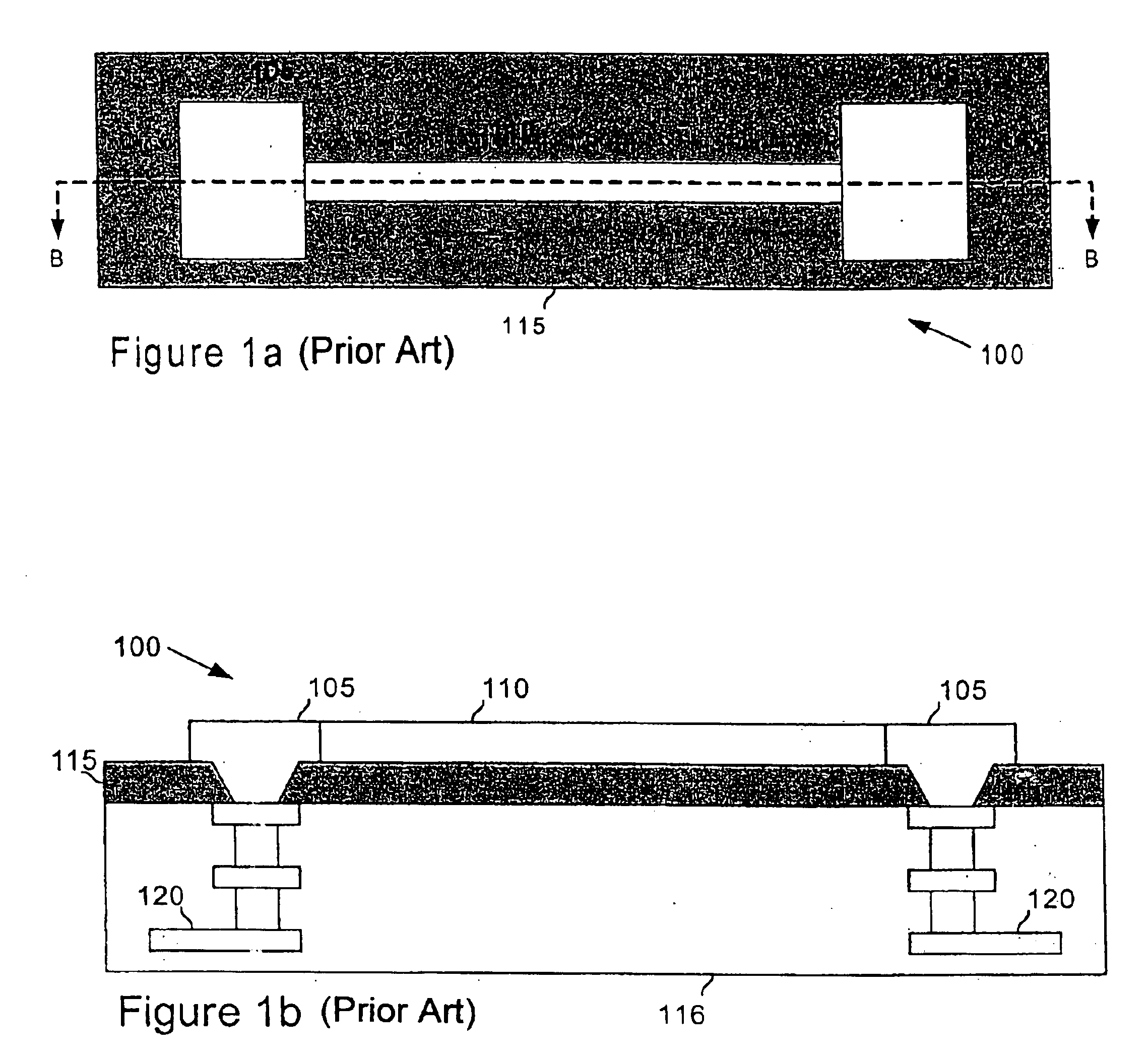
Referring now to FIG. 1a, the diagram illustrates a top view of an unpassivated laser fuse 100 on a hard dielectric layer 115 which lies on top of a substrate 116 (not seen in FIG. 1a, but present in a cross-sectional view presented in FIG. 1b), As discussed previously, an unpassivated laser fuse differs from a passivated laser fuse in that it lacks a passivation layer that protects it from its environment. When compared to a passivated laser fuse, an unpassivated laser fuse requires a less powerful laser to blow its fuse. This is due to the fact that a laser does not have to first pass through ...


PUM


Abstract

The act of blowing an unpassivated electrical fuse (for example, fuse 405) using a laser can result in the splattering of the fuse material and result in electrical short circuits. A blast barrier (for example blast barrier 406) formed around an area of the fuse that is blown by the laser helps to contain the splattering of the fuse material. The blast barrier may be formed from the same material as the fuses themselves and, therefore, can be created in the same fabrication step.

Description

FIELD OF THE INVENTIONThis invention relates generally to integrated circuit fabrication and particularly to the prevention of splattered fuse material created during the blowing of unpassivated laser fuses.BACKGROUND OF THE INVENTIONLaser fuses have been used for an extended period of time in the fabrication of integrated circuits. One application of laser fuses is the activation and deactivation of specific functions in an integrated circuit, depending upon intended use of the integrated circuit. For example, a single design for an integrated circuit may be created with a complete set of functionality. However, depending on the price for which the integrated circuit sells, certain functions may be disabled. In another application, the laser fuses permit the replacement of faulty devices and circuits in the integrated circuit with replacement devices and circuits that are operating properly. Typically, when an integrated circuit undergoes testing to verify its operation, faulty por...

Claims


Application Information

Patent Timeline
IPC IPC(8): H01L23/52H01L23/525
CPCH01L23/5258H01L2924/0002H01L2924/00H01L27/02
Inventor FRIESE, GERALD R.COWLEY, ANDYFAYAZ, MOHAMMED FAZILMOTSIFF, WILLIAM T.
Owner INFINEON TECH AG
Why Eureka
Try Eureka