
Gas discharge panel

a technology of gas discharge panel and gas discharge electrode, which is applied in the direction of gas discharge electrode, gas discharge vessel/container, gas discharge tube, etc., can solve the problems of reducing image quality, brightness decline, and reducing luminescence efficiency, and achieve excellent display capacity in terms of brightness, luminescence efficiency, blackness ratio, contrast

Inactive Publication Date: 2005-03-29
PANASONIC CORP
View PDF13 Cites 14 Cited by
  • Summary
  • Abstract
  • Description
  • Claims
  • Application Information

AI Technical Summary

Benefits of technology

[0034]In view of the issues discussed above, a first object of the present invention is to provide a gas discharge panel with excellent display capacity in terms of brightness, luminescence efficiency, blackness ratio, and contrast.

Problems solved by technology

Thus, although power input and also brightness is increased by increasing the applied voltage (sustain voltage) in the sustain period, luminescence efficiency declines.
However, when the interval between short bars has a regular periodicity, moire occurs on the display surface, and image quality is drastically reduced, this being a major problem.
However, while it is possible to reduce the discharge current by making the entire electrode surface area as small as possible when auxiliary ribs 12 are not provided, brightness declines because of the overall reduction in power supplied in the discharge space.
However, if the height hb is too low, brightness declines markedly.

Method used


Image

  • Gas discharge panel
  • Gas discharge panel
  • Gas discharge panel

Examples


embodiment 8

ccording to embodiment 8;

[0057]FIG. 19 shows a relationship between power and brightness in a vicinity of an auxiliary rib according to embodiment 8;

[0058]FIG. 20 is a cross-sectional view of a PDP according to an embodiment 9;

[0059]FIG. 21 is a cross-sectional view of a PDP according to an embodiment 10;

[0060]FIG. 22 is a cross-sectional view of a PDP according to an embodiment 11;

[0061]FIG. 23 shows a variation of the auxiliary rib;

[0062]FIG. 24 is a cross-sectional view of a PDP according to an embodiment 12;

[0063]FIG. 25 is a cross-sectional view of the PDP showing a variation of embodiment 12;

[0064]FIG. 26 is a cross-sectional view of a PDP according to an embodiment 13;

[0065]FIG. 27 is a cross-sectional view of the PDP showing a variation of embodiment 13;

[0066]FIG. 28 is a partial cross-sectional perspective view of a main structure of a conventional AC-type surface discharge PDP;

[0067]FIG. 29 shows a matrix formed from plural pairs of display electrodes 4 and 5 (N rows) and ...


PUM


Abstract

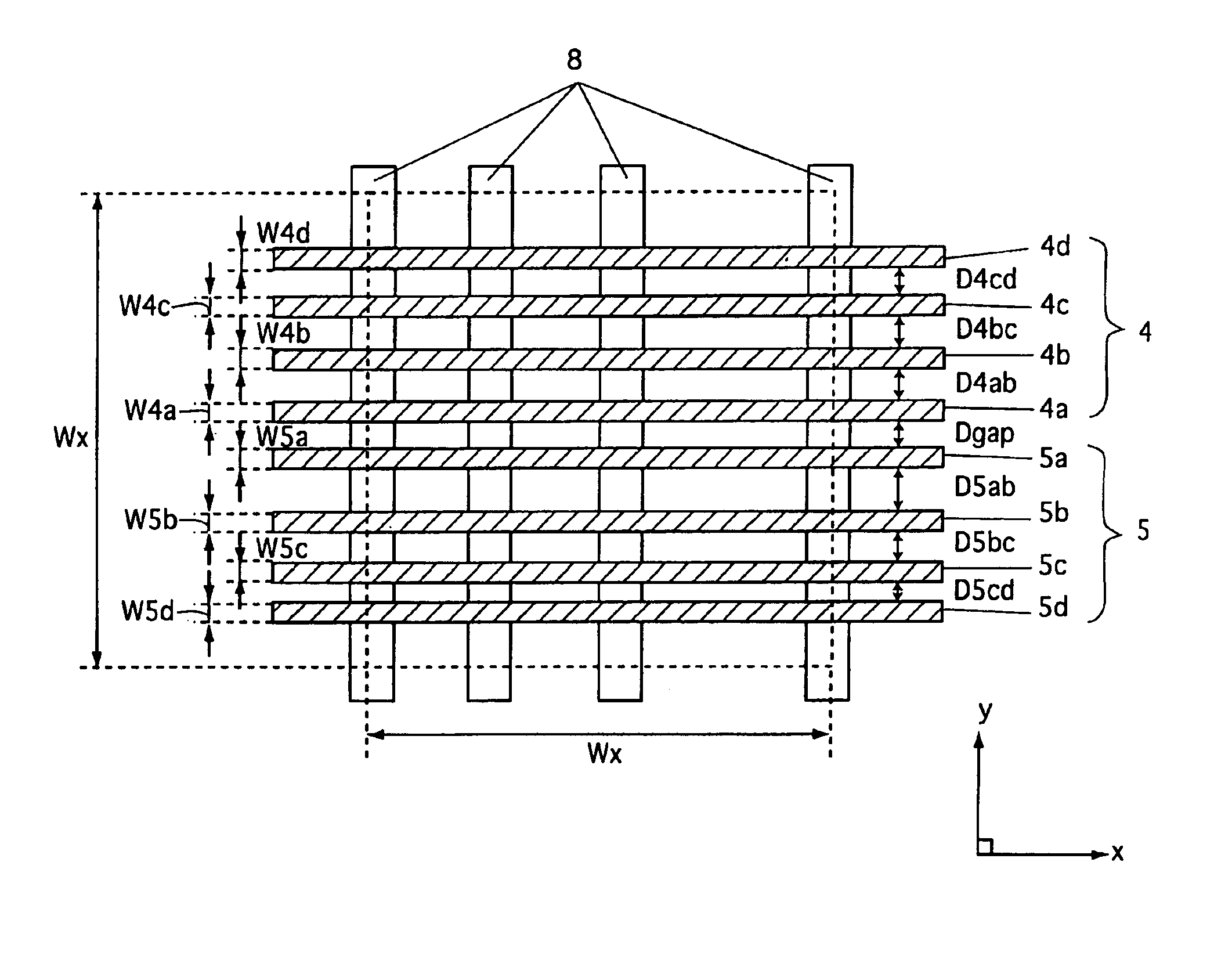
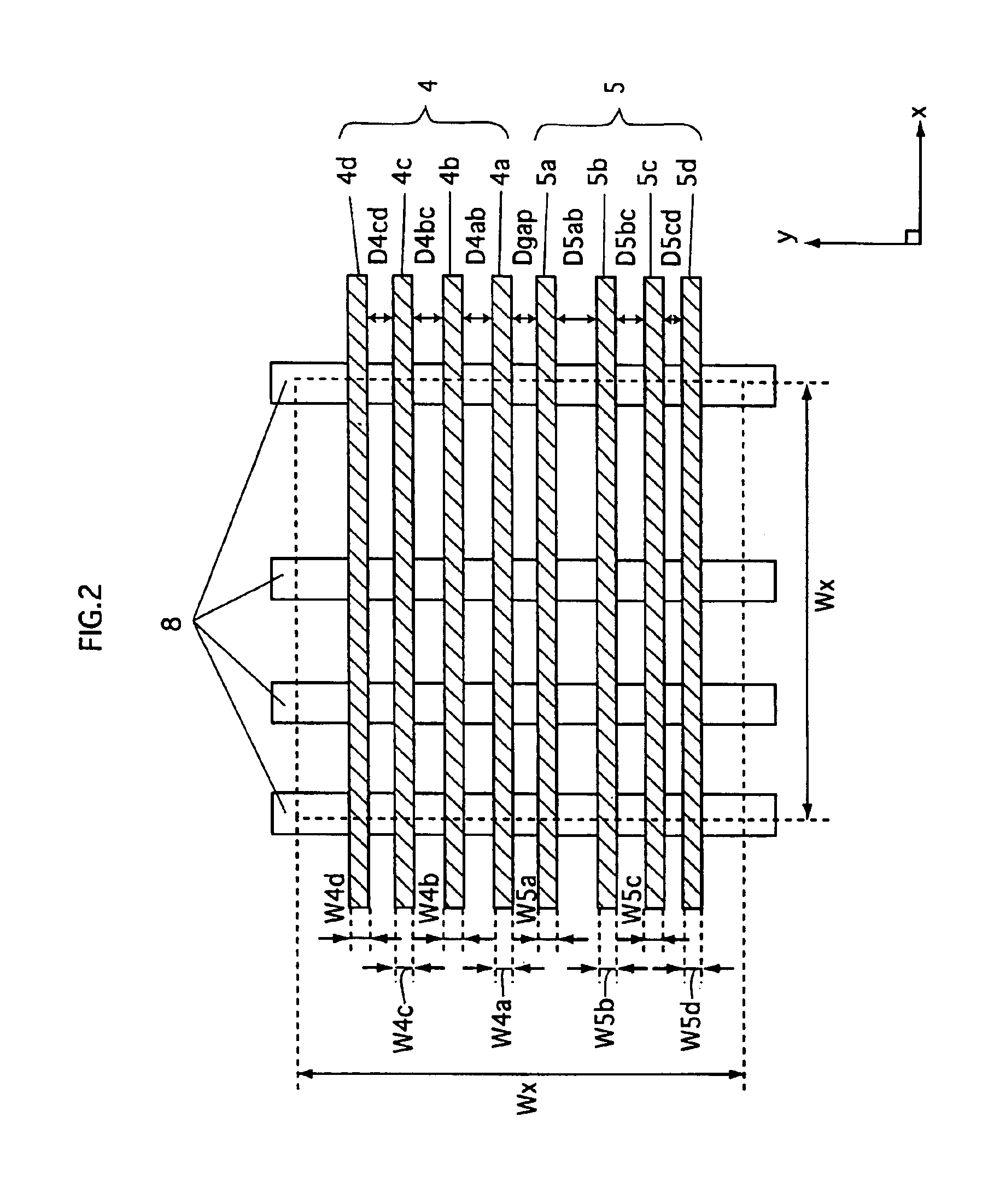
A gas discharge panel having plural pairs of display electrodes disposed so as to extend through a plurality of cells, each pair being formed from a sustain electrode and a scan electrode. The sustain and scan electrodes each include a plurality of line parts, and an aggregate width of the line parts included in the sustain and scan electrodes is in a range of 22% to 48% inclusive of pixel pitch.

Description

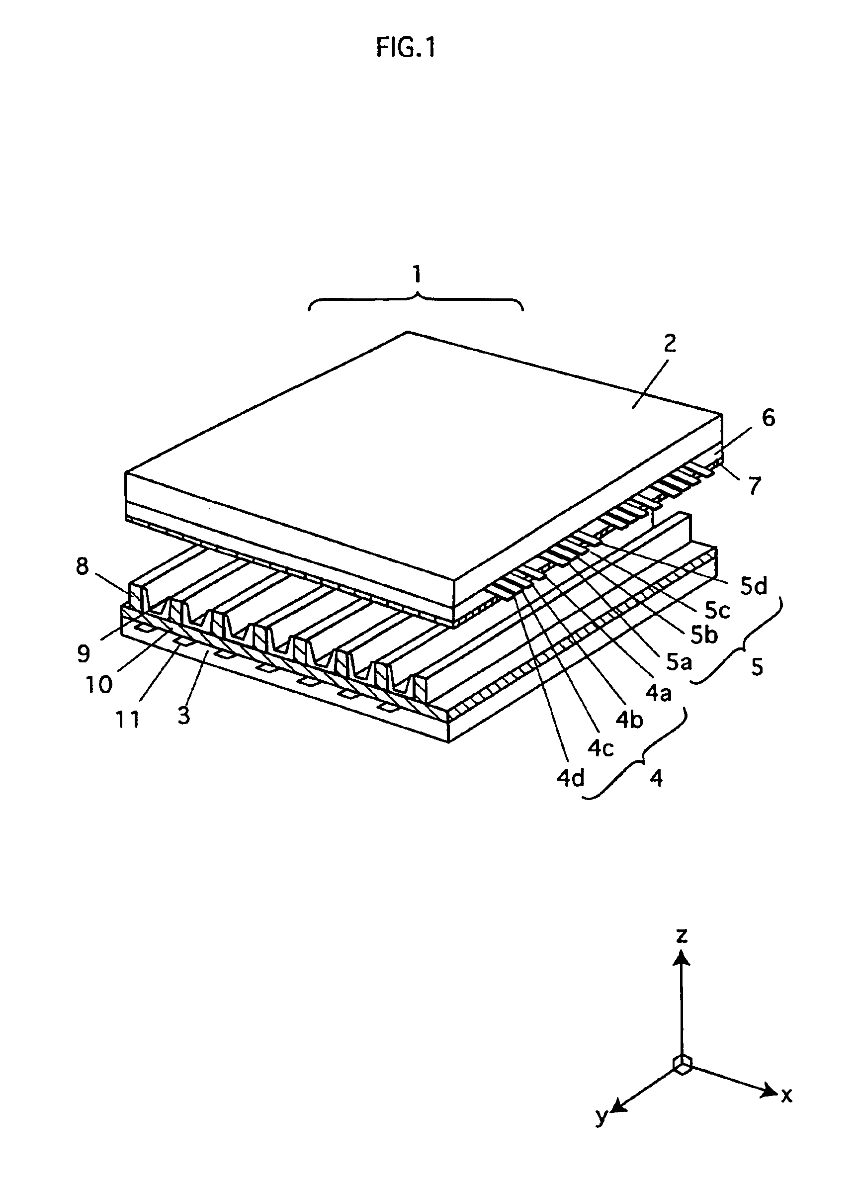
TECHNICAL FIELD[0002]The present invention relates to gas discharge panels such as plasma display panels.BACKGROUND ART[0003]Plasma display panels (PDPs) are one type of gas discharge panel, and they are attracting attention as the display panels of the future due to their short depth and the comparative ease with which screen size can be increased. At present, 60-inch class models are available on the market.[0004]FIG. 28 is a partial cross-sectional perspective view of a main structure of a conventional AC-type surface discharge PDP. In FIG. 28, the z direction corresponds to a thickness of the PDP, and the xy plane corresponds to a plane that is parallel with a panel surface of the PDP. As shown in FIG. 28, PDP 1 is structured from a front panel FP and a back panel BP that are arranged with main surfaces facing each other.[0005]On a main surface of a front panel glass 2 that forms a substrate of front panel FP, plural pairs of display electrodes 4 and 5 (scan electrode 4, sustain...

Claims


Application Information

Patent Timeline
IPC IPC(8): H01J17/49H01J17/04H01J11/44H01J11/24
CPCH01J11/12H01J11/24H01J11/32H01J11/36H01J2211/444H01J2211/245H01J2211/323H01J11/44
Inventor TAKADA, YUUSUKEANDO, TORUNAGAO, NOBUAKIHIGASHINO, HIDETAKANISHIMURA, MASAKIMURAI, RYUICHIWATANABE, YOSHIOKOSUGI, NAOKITACHIBANA, HIROYUKIWANI, KOICHI
Owner PANASONIC CORP
Learn More