Motor vehicle driving aid system

a technology for driving aids and motor vehicles, applied in the direction of braking systems, pedestrian/occupant safety arrangements, instruments, etc., can solve problems such as automatic braking of motor vehicles

Inactive Publication Date: 2005-03-29
ARJO WIGGINS SECURITY SAS +1
View PDF10 Cites 28 Cited by
  • Summary
  • Abstract
  • Description
  • Claims
  • Application Information

AI Technical Summary

Benefits of technology

cause activation of the brake actuator means to ef

Problems solved by technology

Such known systems tend essentially to cause automatic braking of a motor vehicle only on

Method used


Image

  • Motor vehicle driving aid system
  • Motor vehicle driving aid system
  • Motor vehicle driving aid system

Examples


Embodiment Construction

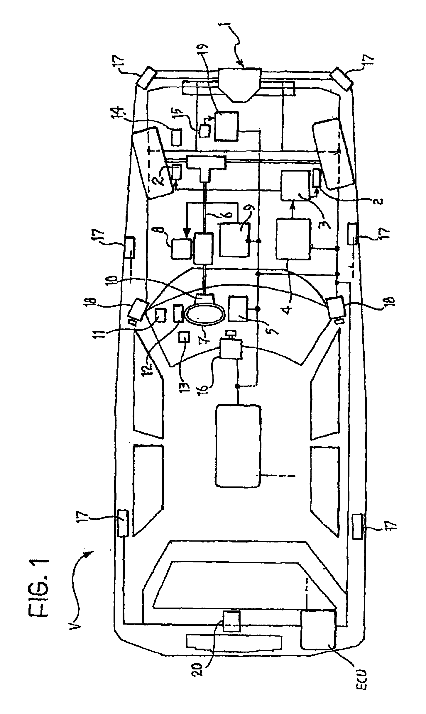
In FIG. 1 the reference V generally indicates a motor vehicle provided with a driving aid system according to the invention.

As will become more clearly apparent hereinafter in the description, a driving aid system according to the invention can be formed in such a way that it is able to perform one or more of a plurality of functions. For each of these functions the driving aid system requires that the motor vehicle V be provided with a particular plurality of devices. Such devices can be shared for the performance of different functions.

With reference to FIG. 1 the devices necessary to have on board the vehicle V for the purpose of being able to perform all the functions which will be described hereinafter will now be described. It will, however, be clear from the following description, as well as from the attached claims, which devices are specifically necessary for the performance of each specific function.

A first function performed by the driving aid system is that of “Emergency...


PUM


Abstract

The system comprises: detector devices (1) operable to provide electrical signals indicative of the relative distance and relative speed of the motor vehicle (V) with respect to a fixed or moving obstacle (O) ahead, and a processing and control unit (ECU) connected to such detector devices (1) as well as to brake actuators (2-4) and arranged to cause activation of the brake actuators (2-4) to effect automatic emergency braking of the motor vehicle (V) when the relative distance between the motor vehicle (V) and an obstacle (O) ahead lies between a first predetermined limit value (dF) equal to the minimum value at which it is still possible to avoid collision by braking and a preselected intermediate value (dE) comprised between said first limit value (dF) and a second limit value (dEcrit) which is less than the said first limit value (df) and is equal to the minimum relative distance value at which it is still possible to follow a path which avoids the obstacle (O), or when the relative distance (dR) becomes less than said second limit value (dEcrit).

Description

BACKGROUND OF THE INVENTIONThe present invention relates to a motor vehicle driving aid system, and in particular a system operable to avoid the occurrence of accidents or at least to limit their consequences, and in particular operable to avoid collisions against obstacles ahead and prevent the vehicle leaving the road.Numerous systems have already been proposed for automatic vehicle braking. Such known systems tend essentially to cause automatic braking of a motor vehicle only on the basis of the relative distance and relative speed with respect to an obstacle ahead.SUMMARY OF THE INVENTIONThe object of the present invention is to provide an improved motor vehicle driving aid system provided with electrically-controlled brake actuator means.According to a first aspect of the invention this object is achieved with a system comprisingfirst detector means operable to provide electrical signals indicative of the relative distance and relative speed of the motor vehicle with respect to...

Claims


Application Information

Patent Timeline
IPC IPC(8): B60K31/00B60T7/22B60R21/00B60T7/12B60W10/00B60W10/04B60W10/20B60W30/08B60W30/16F02D29/02G08G1/16
CPCB60K31/0008B60T7/22B60W10/06B60W10/08B60W30/08B60W30/16B60W30/12B60W2550/402B60W2540/10B60W2540/12B60W2550/20B60W2556/50B60W2554/00B60W2554/804B60W2554/802
Inventor ALBERO, DOMENICOANTONELLO, PIER CLAUDIOCAMPO, SEBASTIANOCHINU, ANGELACICILLONI, RENZOCITELLI, SILVIAMIGLIETTA, MAURIZIOMURDOCCO, VINCENZOQUENDA, VALTERSAROLDI, ANDREA
Owner ARJO WIGGINS SECURITY SAS
Why Eureka
Try Eureka