Expansion unit, portable data processing apparatus and imaging device

a data processing apparatus and portable technology, applied in the direction of electrical apparatus casings/cabinets/drawers, instruments, printers, etc., can solve the problems of not being portable, difficult to carry the apparatus comfortably, and not being able to disconnect the ccd imaging devi

Inactive Publication Date: 2005-03-29
FUJITSU LTD +1
View PDF22 Cites 95 Cited by
  • Summary
  • Abstract
  • Description
  • Claims
  • Application Information

AI Technical Summary

Benefits of technology

Accordingly, it is a general object of the present invention to provide an improved and useful expansion unit, portable data processing apparatus and imaging device for same, in which the above-described disadvantages are eliminated.
According to the invention described above, the imaging device can be panned, or moved laterally, as well as moved vertically, thus improving the ease with which the imaging device can be used and expanding its range of use.

Problems solved by technology

However, each of these examples has disadvantages.
No. 7-322117, when the PC card is inserted into the apparatus the CCD imaging device protrudes from a side of the apparatus, making it difficult to carry the apparatus comfortably.
Also, disconnecting the CCD imaging device is not a practical solution because once disconnected from the apparatus the CCD imaging device cannot be used.
Moreover, the structure disclosed in Japanese Registered Utility Model No. 3011657 is not portable, and the electronic imaging device unit is fixedly mounted to the PC bay and cannot be detached therefrom.
Also, since the electronic imaging device cannot be detached from the electronic imaging device unit the use of the imaging device is severely limited.
Additional problems also beset the above-described conventional structures.
Accordingly, a person using the CCD imaging device 11 must reposition the entire laptop PC 10 in order to photograph a person next to the person using the imaging device, which is inconvenient.
In addition, when the display member 12 is closed an operator's fingers can come into contact with and thereby damage the lens of the CCD imaging device 11.
A further disadvantage is that the positioning of the CCD imaging device 11 on the display member 12 complicates repair of the CCD imaging device 11.
As a result the display member is supported along only approximately half its length, which is unstable and therefore undesirable.
At those times, the inclusion of the imaging device is also an unnecessary expenditure of equipment and space.

Method used


Image

  • Expansion unit, portable data processing apparatus and imaging device
  • Expansion unit, portable data processing apparatus and imaging device
  • Expansion unit, portable data processing apparatus and imaging device

Examples


first embodiment

For clarity, a brief description will be given of a CCD imaging device expansion unit according to the present invention.

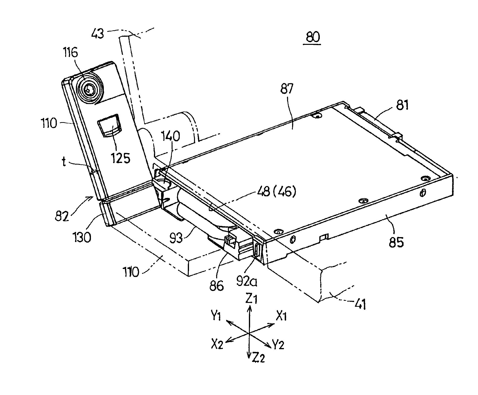
FIG. 4 is a diagram showing a CCD imaging device expansion unit 80 as well as other expansion units (such as a floppy disk expansion unit 60 and so on) together with a laptop-type PC 40 according to a first embodiment of the present invention.

The laptop-type PC 40 shown in FIG. 4 comprises a main unit 41 and a display unit 43 swingingly connected to the main unit 41 via a hinge unit 42. For convenience, an X1, X2 direction denotes a width direction of the PC 40 side to side, a Y1, Y2 direction denotes a depth direction front to back of the PC 40, and a Z1, Z2 direction denotes a vertical direction top to bottom of the PC 40.

In addition, the main unit 41 of the PC 40 has a keyboard area 44 on a top surface thereof, a CPU 45 built into the interior of the main unit 41 and an expansion bay 46 formed as a storage space in a bottom surface of the main unit 41. The expa...


PUM


Abstract

An expansion unit capable of being detachably mounted to an expansion bay of an information processing apparatus, the expansion unit including an imaging device, a moving member moving the imaging device between a state in which the imaging device is stored inside the expansion unit and a state in which the imaging device projects outwardly from the expansion unit, and a member capable of changing a direction in which the imaging device is pointed when the imaging device is extended from the expansion unit, the imaging device being detachable from the expansion unit and supportable in such detached state.

Description

BACKGROUND OF THE INVENTION1. Field of the InventionThe present invention relates generally to an expansion unit, portable data processing apparatus and imaging device.2. Description of the Related ArtRecent advances in portable information processing apparatuses such as laptop-type personal computers (hereinafter PCs) have made it possible to send photographic data via e-mail using such PCs. In addition, the number of types of recording media has also increased and now varies from floppy disks to CD-ROMs, optical disks and so forth.In order to provide these enhanced capabilities and accommodate this expanding array of recording media, laptop PCs have come to be provided with one or more expansion slots and / or a concave expansion bay capable of accommodating detachable accessories including, but not limited to, floppy disk drives, expansion CD-ROM drives, expansion magneto-optic disk drives and the like. Consumers are thus able to purchase add-on accessories as discrete modules or e...

Claims


Application Information

Patent Timeline
Patent Type & Authority Patents(United States)
IPC IPC(8): H04N5/225G03B17/02G06F15/02G06F1/16
CPCG03B29/00H04N5/2251G06F1/1632G06F1/1607H04N23/50
Inventor KANBE, KATSUHITOFUCHIDA, HIDEHIKOYOSEYAMA, TOSIOMAEDA, MITSUO
Owner FUJITSU LTD
Why Eureka
Try Eureka