Length measure apparatus and the method for measuring

Inactive Publication Date: 2005-03-29
LIH RURNG INSTR TRADING
View PDF6 Cites 5 Cited by
  • Summary
  • Abstract
  • Description
  • Claims
  • Application Information

AI Technical Summary

Benefits of technology

The main objective of the present invention is to provide an improved measure apparatus and the method for measuring that can overcome errors from the operator's vision and the measure apparatus.

Problems solved by technology

However, the width of the standard line will cause an error the same as the embodiment described above.

Method used


Image

  • Length measure apparatus and the method for measuring
  • Length measure apparatus and the method for measuring
  • Length measure apparatus and the method for measuring

Examples


Embodiment Construction

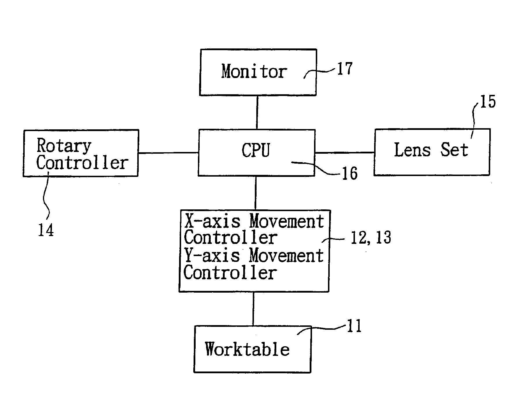
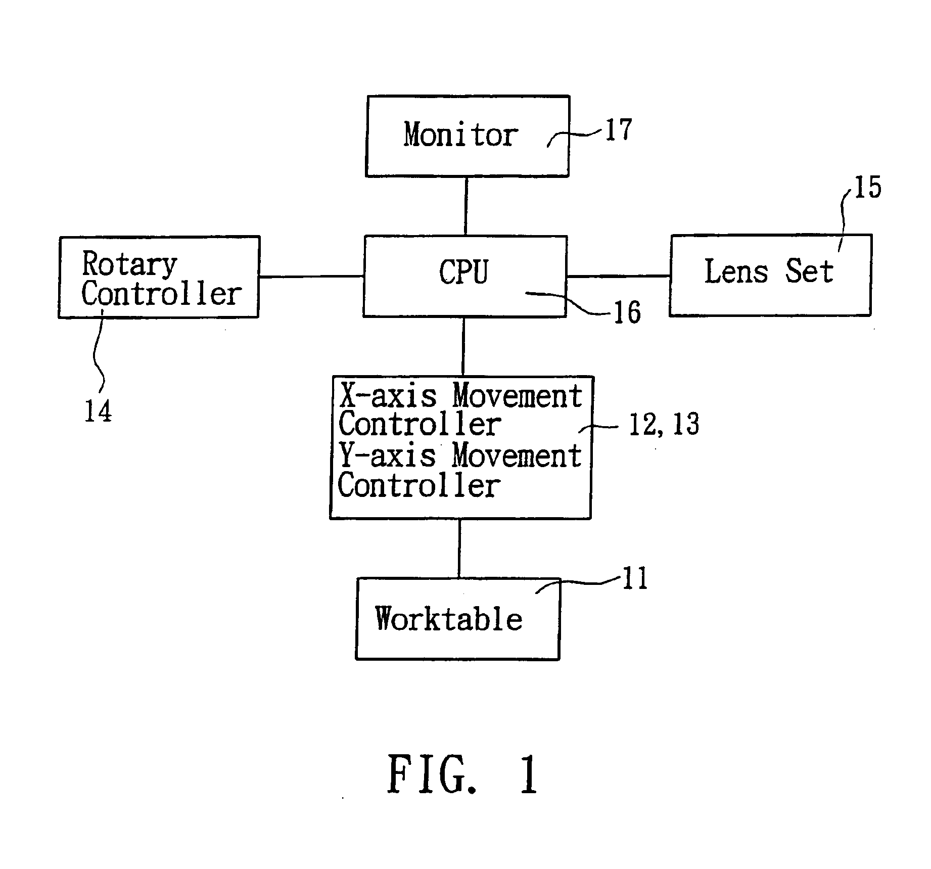
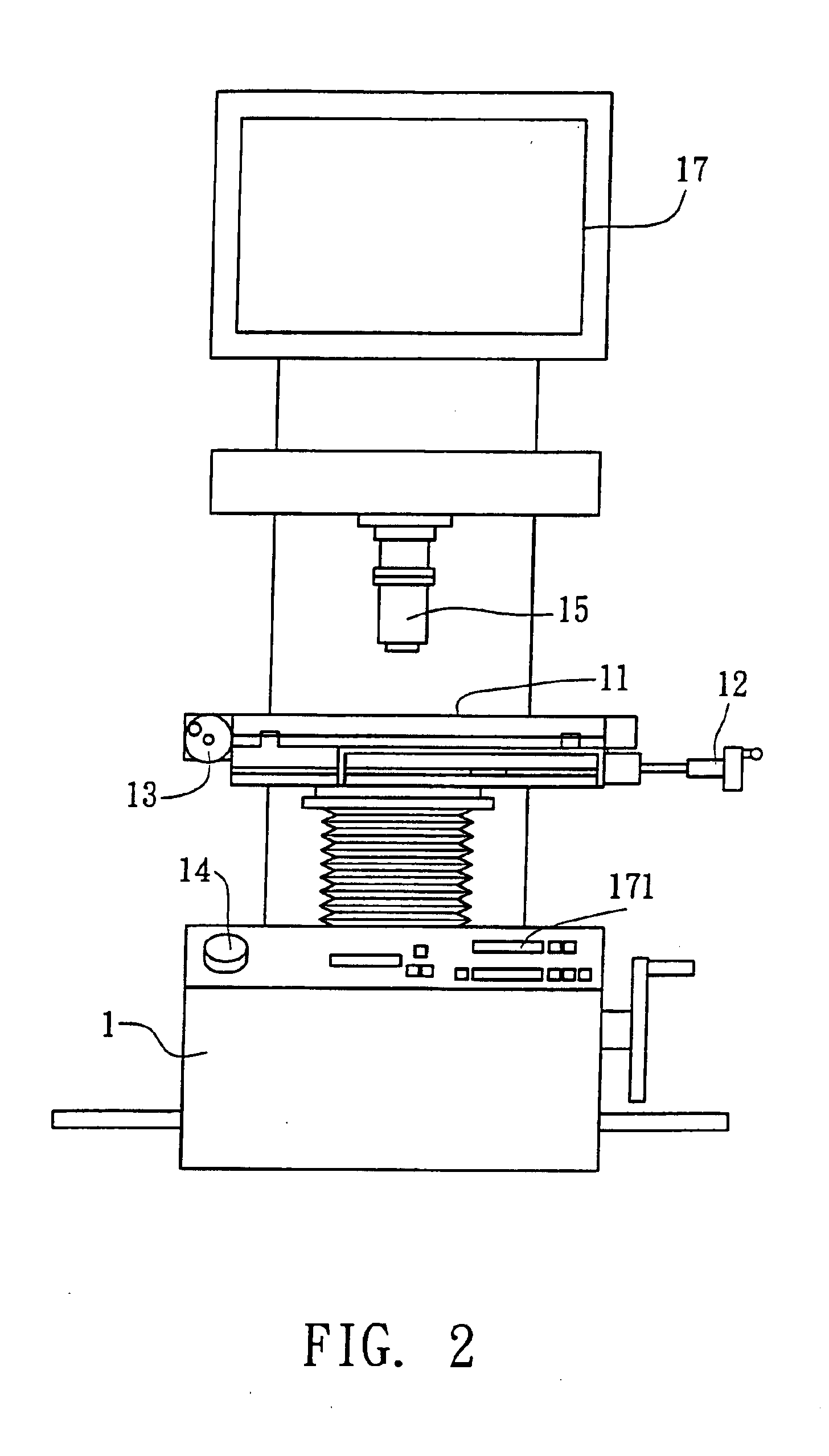
Referring to the drawings and initially to FIGS. 1-3, a length measure apparatus in accordance with the present invention comprises a base member (1) and a worktable (11) moveably mounted on the base member (1). An X-axis movement controller (12) is mounted to the worktable (11) for controlling the movement of the worktable (11) relative to the X-axis of the worktable (11) and a Y-axis movement controller (13) is mounted to the worktable (11) for controlling the movement of the worktable (11) relative to the Y-axis of the worktable (11).

A lens set (15) is mounted to the length measure apparatus and located above the worktable (11) for collecting the images of the workpiece that is put on the worktable (11). In the preferred embodiment of the present invention, the lens set (15) is a CCD or a CMOS image collect module.

A central processing unit (CPU) (16, not shown) in received in the base member (1) and electrically connected to the lens set (15) for executing a digital process to th...


PUM


Abstract

A length measure apparatus and the method for measuring transform an image from a lens set into a digital contrast image via a central processing unit. The CPU has multiple standard lines that are previously set therein. Multiple movement controllers control a movement of a selected standard line from the CPU relative to the digital contrast image. A movement value is output when the selected standard line flushes with a profile of the contrast image. The measure value is shown on a monitor when the CPU contrasts the movement of the selected standard line.

Description

BACKGROUND OF THE INVENTION1. Field of the InventionThe present invention relates to a length measure apparatus and the method for measuring, and more particularly to a length measure apparatus and the method for measuring that can overcome errors from the operator's vision and the measure apparatus.2. Description of Related ArtA conventional profile projector in accordance with the prior art shown in FIG. 5 comprises a base member (81) and a worktable (82) mounted on the top of the base member (81). A project box (83) is mounted to the top of the worktable (82). A screen (84) is rotatably attached to the project box (83) and made of frosted glass. Multiple clamps (841) are mounted on the project box (83) around the screen (84) for securing a transparent film on the screen (84). A adjust knob (85) is rotatably mounted to the project box (83) for rotating the screen (84). A first adjust roller (86) is pivotally mounted to the worktable (82) for reciprocally moving the worktable (82) ...

Claims


Application Information

Patent Timeline
Patent Type & Authority Patents(United States)
IPC IPC(8): G01B11/02G01B9/04
CPCG01B11/02G01B9/04
Inventor HUANG, YI-SHIH
Owner LIH RURNG INSTR TRADING
Why Eureka
Try Eureka