MAC address population protocol

a technology of address population and network packets, applied in data switching networks, multiplex communication, digital transmission, etc., can solve the problems of large amount of network bandwidth consumed by various search messages, situation becomes progressively worse, etc., and achieves the effect of reducing the consumption of network bandwidth and no need to waste bandwidth

Inactive Publication Date: 2005-03-29
CISCO TECH INC
View PDF8 Cites 47 Cited by
  • Summary
  • Abstract
  • Description
  • Claims
  • Application Information

AI Technical Summary

Benefits of technology

The invention reduces the consumption of network bandwidth by transmission of search messages by routers. The invention is a new search protocol using a message which a router periodically transmits onto the local LANs connected to its ports, and in response to the new protocol, all end stations receiving the message transmit their addresses to the router. The addresses transmitted to the router comprise the addresses and any other information needed by the router to reach the end station. For example, for an Ethernet LAN the layer 2 or MAC layer address of the end station is transmitted to the router. In the event that the protocol of the LAN uses source routing, the information transmitted to the router includes both the MAC address of the end station and the Route Information Field needed to reach the end station. In any event, the router uses the information received from the end stations to build its bridge table. Then, upon receipt of the next CANUREACH message from a peer router, the desired destination end station will appear in the router's bridge table, and there will be no need to waste bandwidth by transmitting search messages looking for the end station. The new protocol messages are transmitted periodically in order to keep the bridge tables current as the network changes dynamically.

Problems solved by technology

This situation becomes progressively worse when many stations on LAN 1 try to talk to different stations, including those stations on LAN2, and on other LANs.
The result is that a large amount of network bandwidth is consumed by the various search messages.

Method used


Image

  • MAC address population protocol
  • MAC address population protocol
  • MAC address population protocol

Examples


Embodiment Construction

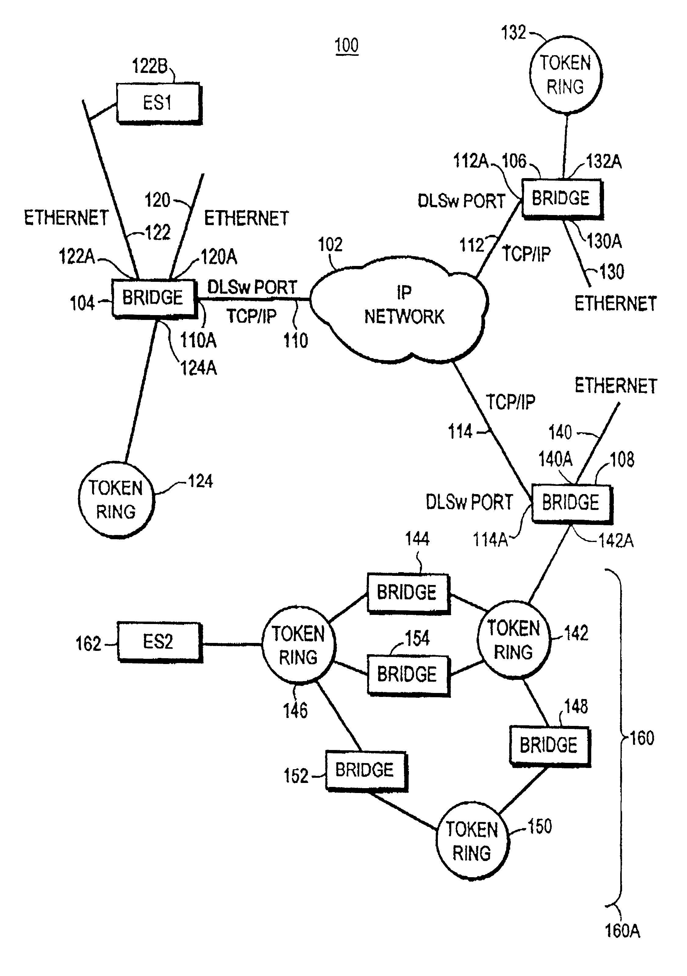
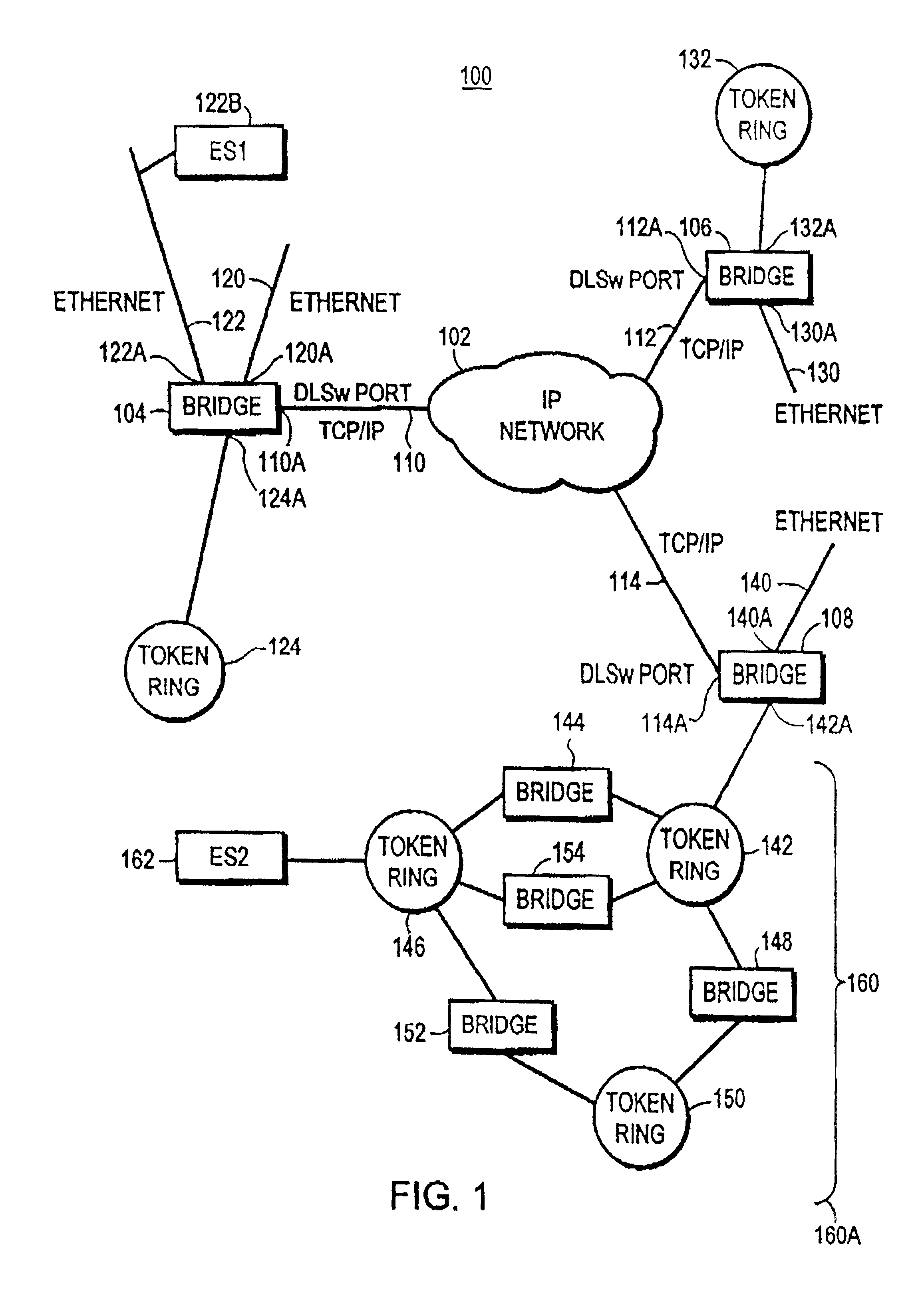
Turning now to FIG. 1, computer network 100 is shown. Network Cloud 102 supports TCP / IP protocol communication between stations connected thereto. Bridge 104, bridge 106, and bridge 108 provide Layer 2 bridging between Local Area Networks (LANs) connected to ports of the respective bridges. Bridges 104, 106, 108 have ports providing TCP / IP protocol communication through network cloud 102, and these bridges have their TCP / IP ports connected to network cloud 102. The DLSw ports of bridges 104, 106, 108 are operated by a routing function in bridges 104, 106, 108. For example, bridge 104 has it's TCP / IP port 110A connected by link 110 to Network cloud 102, bridge 106 has its TCP / IP port 112A connected to network cloud 102 by link 112, and bridge 108 is connected at its DSLw port 114A by link 114 to network cloud 102. Communication using TCP / IP protocol through a DLSw connection, can be established between bridges 104, 106, 108 through network cloud 102. Also communication using TCP / IP p...


PUM


Abstract

A new search protocol uses a message which a router periodically transmits onto the local LANs connected to its ports, and in response to the new protocol, all end stations receiving the message transmit their addresses to the router. The addresses transmitted to the router comprise the addresses and any other information needed by the router to reach the end station. For example, for an Ethernet LAN the layer 2 or MAC layer address of the end station is transmitted to the router. In the event that the protocol of the LAN uses source routing, the information transmitted to the router includes both the MAC address and the Route Information Field of the end station. In any event, the router uses the information received from the end stations to build its routing table. Then, upon receipt of the next CANUREACH message from a peer router, the desired destination end station will appear in the router's routing table, and there will be no need to waste bandwidth by transmitting search messages looking for the end station. The new protocol messages are transmitted periodically in order to keep the routing tables current is as the network changes dynamically.

Description

FIELD OF THE INVENTIONThis invention relates to bridging packets in computer networks, and more particularly to establishing bridge tables while reducing network bandwidth consumed by establishing the bridge tables.BACKGROUND OF THE INVENTIONA bridge maintains a table (the bridge table) of end stations connected to local area networks having connections to ports of the bridge. When a frame arrives at the bridge, and the frame has a Layer 2 destination address (DA) different from the Layer 2 address of the bridge, the bridge consults its bridge table, determines from the bridge table which port of the bridge to bridge the frame to in order for the frame to reach the destination end station, and transmits the frame to the LAN connected to that port.In the event that a data frame, or a TEST frame, arrives at a bridge and the destination address of the frame does not appear in the bridge table of the bridge, then the bridge learns the source MAC address from the frame if it is not alrea...

Claims


Application Information

Patent Timeline
Patent Type & Authority Patents(United States)
IPC IPC(8): H04L12/56H04L12/46
CPCH04L45/02H04L12/4625
Inventor IVATURI, DEVI PRASAD
Owner CISCO TECH INC
Why Eureka
Try Eureka