Storage system and data transfer control method

a storage system and data transfer technology, applied in the field of data transfer, can solve the problems of excessive consumption of network bandwidth between each site and the central data center, inability to perform fine granularity management, and delay in tasks, so as to reduce the consumption of network bandwidth and suppress the degradation of access performan

Active Publication Date: 2021-03-02
HITACHI LTD
View PDF13 Cites 0 Cited by
  • Summary
  • Abstract
  • Description
  • Claims
  • Application Information

AI Technical Summary

Benefits of technology

[0016]A second host can refer to data in a first site without waiting for all data in the first site to be copied to a second site. Since the data acquired from the first site to the second site by the reference is stored in the second site, the data can be used thereafter. As a result, it can be expected to suppress degradation of access performance in the second site thereafter. Further, an amount of data transferred from the first site to the second site is reduced, so that it is possible to reduce consumption of a network bandwidth.

Problems solved by technology

For this reason, the analysis cannot be started until all data of each site is completely transferred to the central data center, so that there is a problem that utilization of the analysis result in the task is delayed.
In addition, there is a problem that a network bandwidth between each site and the central data center is consumed excessively.
For this reason, it is not possible to perform management of fine granularity of leaving a part of the data in the central data center.
As a result, if analysis processing executed in the central data center accesses data of a remote site, data access of the analysis processing involves data copying between the sites, which results in causing performance degradation of the analysis processing.

Method used


Image

  • Storage system and data transfer control method
  • Storage system and data transfer control method
  • Storage system and data transfer control method

Examples


first embodiment

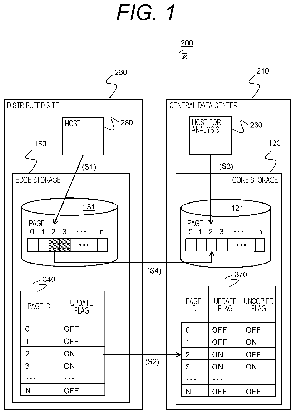
[0056]FIG. 1 is a schematic diagram showing an outline of a first embodiment.

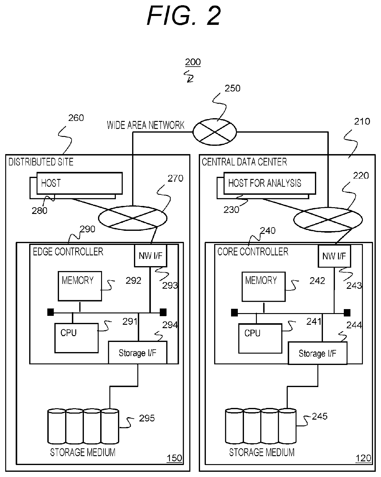
[0057]A computer system 200 has one or more distributed sites 260 (an example of a first site) and one central data center 210 (an example of a second site). Hereinafter, one distributed site 260 will be taken as an example.

[0058]A host computer (hereinafter, referred to as a host) 280 and a storage device (hereinafter, referred to as an edge storage) 150 exist in the distributed site 260. The host 280 is an example of a first host. The edge storage 150 is an example of a first storage device. A host computer for analysis (hereinafter, referred to as a host for analysis) 230 and a storage device (hereinafter, referred to as a core storage) 120 exist in the central data center 210. The host 230 for analysis is an example of a second host and is a host used for analysis. The core storage 120 is an example of a second storage device. A storage system includes the edge storage 150 and the core storage 120.

[0059...

second embodiment

[0142]A second embodiment will be described. Hereinafter, a difference with the first embodiment will be mainly described, and the description of the points common to the first embodiment will be simplified or omitted.

[0143]As at least one of an edge storage and a core storage, instead of a device receiving an access request designating an LUN and an address (for example, a logical block address (LBA)) shown in the first embodiment and accessing data according to the request, a device performing access in a data set unit such as a file and an object may be adopted. Particularly, a form in which a file storage is disposed in each site and data stored in the file storage is copied to a storage system providing data access in an object unit such as a cloud storage may be taken. In the second embodiment, the above form is adopted. The “data set” is one block of logical electronic data viewed from a program such as an application program, and may be, for example, any one of a record, a f...

third embodiment

[0192]A third embodiment will be described. Hereinafter, a difference with the first embodiment will be mainly described, and the description of the points common to the first embodiment will be simplified or omitted.

[0193]In a computer system, data may migrate from an old storage device to a newly purchased storage device. In the present embodiment, even when a storage system processing an access request designating an LUN and an address (for example, an LBA) is in the middle of the data migration, the same effect as that of the first embodiment is realized.

[0194]FIG. 22 is a configuration diagram of a computer system 1400 in the third embodiment.

[0195]The computer system 1400 includes a central data center 210 and one or more distributed sites 1460. The central data center 210 and the distributed site 1460 are connected to each other by a wide area network 250. The central data center 210 has the same configuration as that of the first embodiment. The distributed site 1460 has alm...


PUM


Abstract

When a second storage device in a second site receives an update notification regarding a first element updated according to a write request from a first host, from a first storage device in a first site, for a second element specified on the basis of the update notification, the second storage device manages data of the first element corresponding to the second element as latest data. The first storage device provides a first volume capable of including a plurality of first elements. The second storage device provides a second volume capable of including a plurality of second elements corresponding to the plurality of first elements. When the second storage device receives a read request from a second host, the second storage device determines whether or not data of the first element corresponding to a read source second element (second element specified from the read request) is the latest data. When a determination result is true, the second storage device acquires the latest data from the first storage device and returns the latest data to the second host.

Description

CROSS-REFERENCE TO RELATED APPLICATIONS[0001]This application is a U.S. National Stage entry of PCT Application No: PCT / JP2017 / 028171, filed on Aug. 3, 2017, the contents of which are incorporated herein by reference.TECHNICAL FIELD[0002]The present invention relates generally to data transfer between site (between storage devices).BACKGROUND ART[0003]As applications of a computer system, applications that optimize a task by analyzing data obtained by technology such as Internet of Things (IoT) and stored in a storage device in a site and feeding back an analysis result are known. In such applications, in order to analyze data of a plurality of sites in a central data center in a cross-sectoral manner, the central data center should be able to refer to the data of each site. The “site” is an example of a “first site” and the “central data center” is an example of a “second site”. The “site” (both the first and second sites) mentioned herein refers to a site where a computer system s...

Claims


Application Information

Patent Timeline
Patent Type & Authority Patents(United States)
IPC IPC(8): G06F3/06
CPCG06F3/0655G06F3/067G06F3/0619G06F3/0653G06F3/0683G06F3/061G06F3/065G06F11/14G06F12/00
Inventor TSUCHIYA, AKIYOSHIMATSUZAWA, KEIICHIHAYASAKA, MITSUOYAMAMOTO, AKIRA
Owner HITACHI LTD
Why Eureka
Try Eureka