Distributed flow properties wellbore measurement system

Active Publication Date: 2005-04-05
WELLDYNAMICS BV
View PDF21 Cites 199 Cited by
  • Summary
  • Abstract
  • Description
  • Claims
  • Application Information

AI Technical Summary

Benefits of technology

In carrying out the principles of the present invention, in accordance with an embodiment thereof, a means of determining fluid properties or parameters is provided which is relatively uncomplicated to construct and

Problems solved by technology

Unfortunately, these special sensors are many times very expensive to manufacture, complex, failure-prone, difficult to install, etc.
The noise is due to turbulence in the fluid flow itself.
On

Method used


Image

  • Distributed flow properties wellbore measurement system
  • Distributed flow properties wellbore measurement system
  • Distributed flow properties wellbore measurement system

Examples


Example

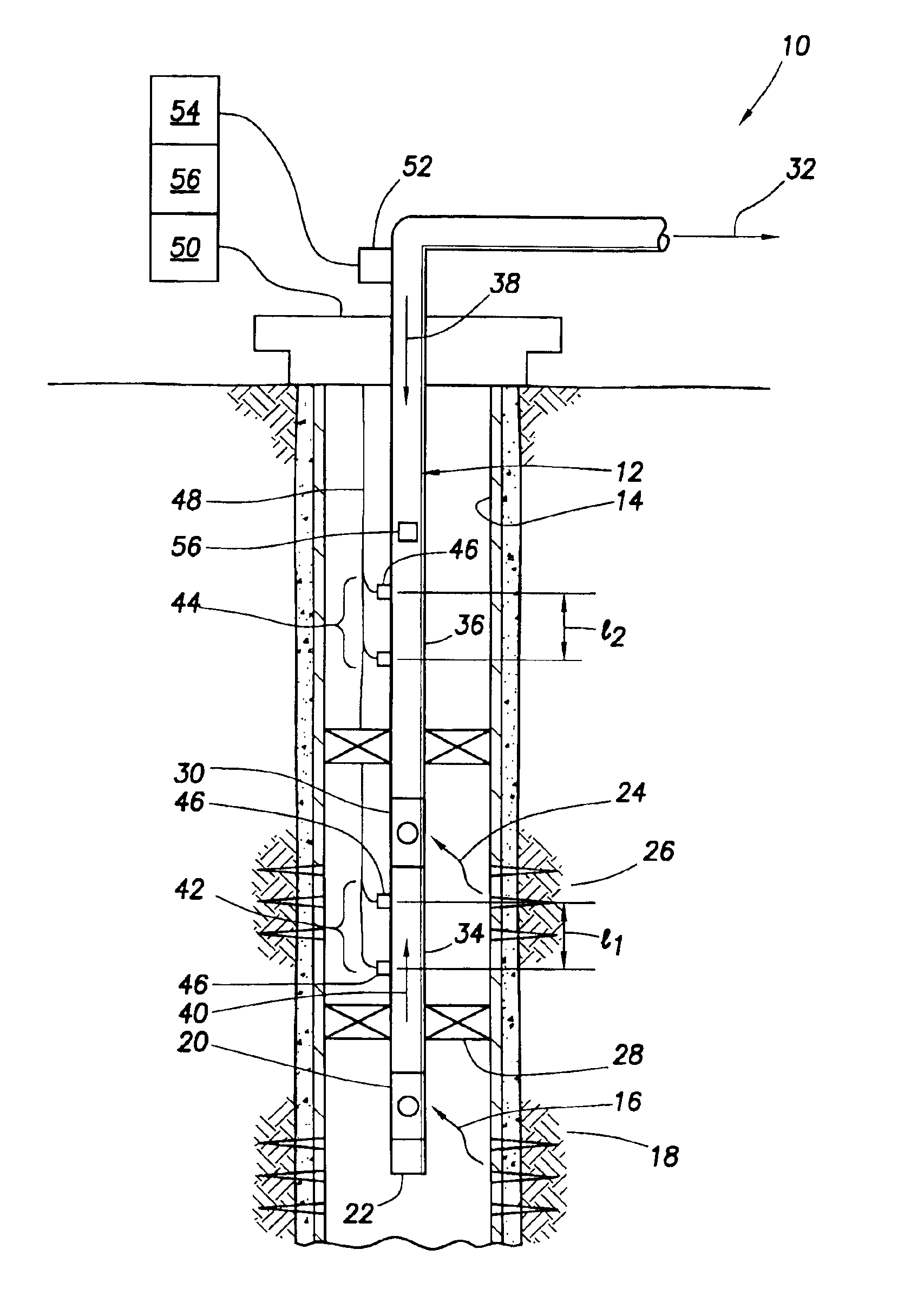
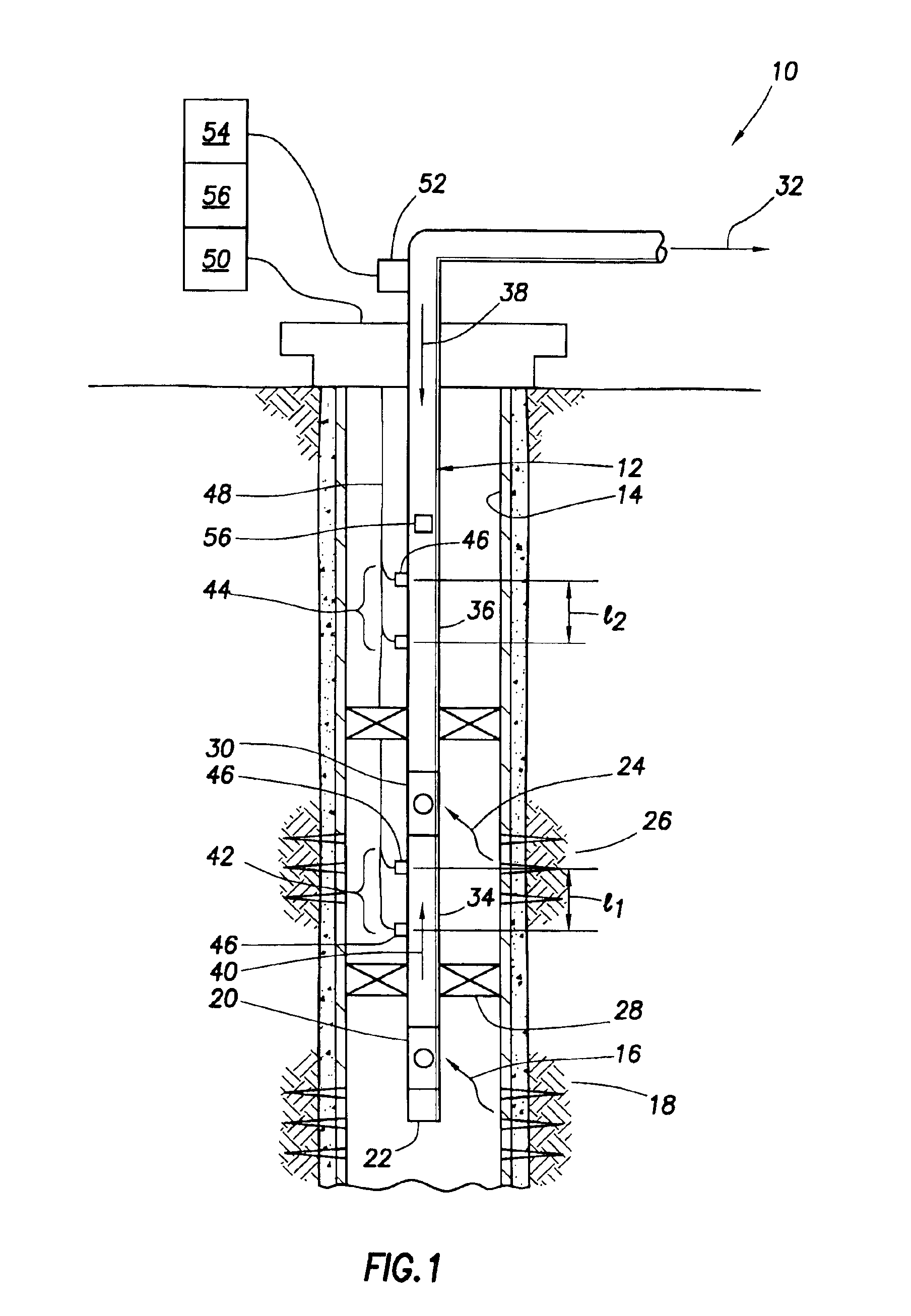
Representatively illustrated in FIG. 1 is a system 10 and associated method which embody principles of the present invention. In the following description of the system 10 and other apparatus and methods described herein, directional terms, such as “above”, “below”, “upper”, “lower”, etc., are used only for convenience in referring to the accompanying drawings. Additionally, it is to be understood that the various embodiments of the present invention described herein may be utilized in various orientations, such as inclined, inverted, horizontal, vertical, etc., and in various configurations, without departing from the principles of the present invention.

As depicted in FIG. 1, the system includes a tubular string 12 positioned in a wellbore 14 of a subterranean well. The tubular string 12 is more specifically known as a production tubing string, but the principles of the invention are also applicable to casing strings, liner strings, coiled tubing strings, or any other type of tubul...


PUM


Abstract

A distributed flow properties wellbore measurement system. In a described embodiment, a system for determining at least one parameter of a fluid in a tubular string includes a pressure pulse generator attached to the tubular string and a set of sensors. The generator transmits a pressure pulse through the fluid. The set of sensors is used to determine a velocity of the pressure pulse transmitted through the fluid, and to determine a velocity of the pressure pulse reflected back through the fluid.

Description

BACKGROUNDThe present invention relates generally to equipment utilized and operations performed in conjunction with subterranean wells and, in an embodiment described herein, more particularly provides a distributed flow properties wellbore measurement system.Fluid flow rates, fluid compositions and other properties can presently be monitored in a well using specially constructed sensors. Unfortunately, these special sensors are many times very expensive to manufacture, complex, failure-prone, difficult to install, etc.One flowmeter known in the art uses frequency sensing transducers to sense ultrasonic noise in fluid flowing through a pipe. The noise is due to turbulence in the fluid flow itself. One disadvantage of this flowmeter is that it relies on the noise (or at least a unique portion of the noise frequency spectrum) continuing substantially unchanged along the length of the pipe.Thus, it may be seen that improved systems and methods for determining fluid properties are need...

Claims


Application Information

Patent Timeline
IPC IPC(8): E21B47/10E21B43/00E21B43/14G01H5/00
CPCE21B43/14G01H5/00E21B47/101E21B47/107
Inventor MELTZ, GERALDSKINNER, NEAL G.
Owner WELLDYNAMICS BV
Why Eureka
Try Eureka