Circular cutter with a friction-provided plate

a friction-provided plate and cutter technology, applied in the field of circular cutters, can solve the problems of loosening of locking bolts, wear of threads in screw holes, and insufficient strength of bracket mounting elements b>12

Inactive Publication Date: 2005-04-05
P & F BROTHER INDAL
View PDF4 Cites 83 Cited by
  • Summary
  • Abstract
  • Description
  • Claims
  • Application Information

AI Technical Summary

Benefits of technology

According to the present invention, a circular cutter includes: a base unit including a base plate having a top face, and a bracket-mounting part that is integrally formed with the base plate as a single piece and that projects uprightly from the top face, the bracket-mounting part defining a first abutting face that is transverse to the top face, and being formed with an inner thread that extends in a transverse direction relative to the first abutting face; a pivot shaft extending in the transverse direction; a bracket pivoted to the bracket-mounting part through the pivot shaft so as to be rotatable about the pivot shaft, defining a second abutting face that confronts the first abutting face, and formed with an arcuate slot that is disposed adjacent to the inner thread; a cutter-holding arm mounted rotatably on the bracket; a friction-providing plate interposed between the first and second abutting faces; and a cutter-tilting lock including a screw rod that extends through the arcuate slot and the friction-providing plate in the transverse direction to threadedly engage the inner thread in such a manner that the friction-providing plate is tightly clamped between the first and second abutting faces when the screw rod is tightened, thereby preventing rotation of the bracket about the pivot shaft, and that the friction-providing plate is relieved from the clamping action when the screw rod is loosened, thereby permitting rotation of the bracket about the pivot shaft.

Problems solved by technology

One disadvantage of the conventional circular cutter resides in that since the base plate 10 is made from aluminum, which is relatively soft, it is not strong enough to hold the bracket-mounting element 12 thereon.
Besides, constant vibration of the bracket 13 relative to the bracket-mounting element 12 during cutting operations may result in loosening of the locking bolts 121 and wear of the threads in the screw holes 112.

Method used


Image

  • Circular cutter with a friction-provided plate
  • Circular cutter with a friction-provided plate
  • Circular cutter with a friction-provided plate

Examples


Embodiment Construction

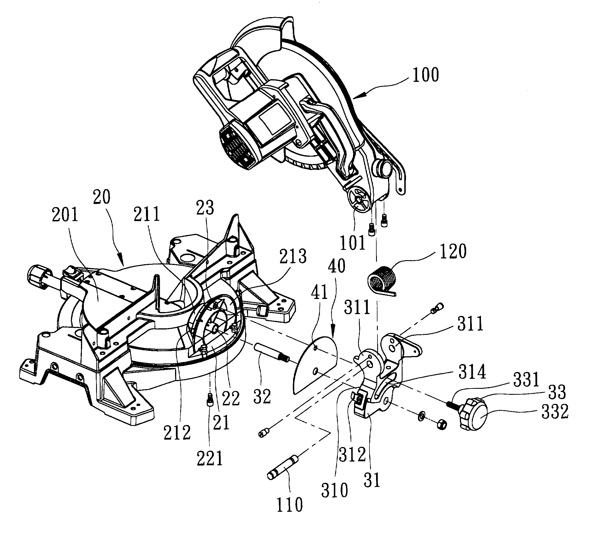
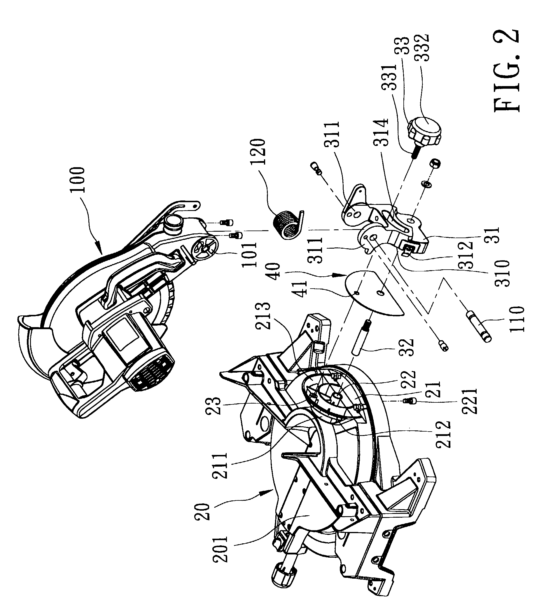
Referring to FIGS. 2 to 4, the preferred embodiment of a circular cutter according to the present invention is shown to include a base unit, a pivot shaft 32, a bracket 31, a cutter-holding arm 100, a sector-shaped friction-providing plate 40 and a cutter-tilting lock 33.

As illustrated, the base unit includes a base plate 20 having a top face 201, and a bracket-mounting part 21 that is integrally formed with the base plate 20 as a single piece and that projects uprightly from the top face 201. The bracket-mounting part 21 defines a first abutting face 213 that is transverse to the top face 201. The bracket-mounting part 21 is formed with an inner thread 23 that extends in a transverse direction relative to the first abutting face 213.

The pivot shaft 32 extends in the transverse direction.

The bracket 31 is pivoted to the bracket-mounting part 21 through the pivot shaft 32 so as to be rotatable about the pivot shaft 32, and defines a second abutting face 310 that confronts the fir...


PUM

PropertyMeasurementUnit
frictionaaaaaaaaaa
tilting angleaaaaaaaaaa

Abstract

A circular cutter includes a bracket-mounting part integrally formed with a base plate as a single piece. The bracket-mounting part defines a first abutting face. A bracket is pivoted to the bracket-mounting part through a pivot shaft. The bracket defines a second abutting face, and is formed with an arcuate slot. A cutter-holding arm is pivoted to the bracket. A friction-providing plate is interposed between the first and second abutting faces. A screw rod extends through the arcuate slot and the friction-providing plate to threadedly engage an inner thread in the bracket-mounting part.

Description

BACKGROUND OF THE INVENTION 1. Field of the Invention The present invention relates to a circular cutter, more particularly to a circular cutter with a tiltable cutter-holding arm which is pivoted to a bracket-holding part of a base plate through a friction-providing plate. 2. Description of the Related Art Referring to FIG. 1, a conventional circular cutter is shown to include a base plate 10, a bracket-mounting element 12, a pivot shaft 132, a bracket 13, a cutter-holding arm 14, and a cutter-tilting lock. The base plate 10 is made from aluminum, and is formed with a recess 111 and a pair of screw holes 112. The bracket-mounting element 12 is made from cast iron, is disposed in the recess 111, and is fixed to the base plate 10 through threaded engagement between two locking bolts 121 and the screw holes 112 in the base plate 10. The bracket-mounting element 12 is formed with an inner thread, and defines a first abutting face that is transverse to the base plate 10. The bracket 13 ...

Claims


Application Information

Patent Timeline
Patent Type & Authority Patents(United States)
IPC IPC(8): B23D45/04B23D45/00B27B5/29B27B5/00
CPCB27B5/29B23D45/044Y10T83/7726Y10T83/7705Y10T83/7697Y10T83/7788Y10T83/7613Y10T83/8773
Inventor CHANG, CHIU-TSUN
Owner P & F BROTHER INDAL
Why Eureka
Try Eureka