Lung simulator

a simulator and lungs technology, applied in the field of lung simulators, can solve the problems of not being able to demonstrate the interaction between the lungs and the fixed masses, not being able to achieve the symmetrical relationship between the fixed masses and the two simulated lungs, and being limited to the devi

Inactive Publication Date: 2005-04-05
ESTETTER ROBERT H +2
View PDF16 Cites 63 Cited by
  • Summary
  • Abstract
  • Description
  • Claims
  • Application Information

AI Technical Summary

Benefits of technology

To address the above-discussed deficiencies of the prior art, the present invention provides a lung simulator comprising a substantially-rigid, fluid-tight, translucent housing simulating a human thoracic cavity and at least one flexible air-tight bag simulating a lung having a plurality of simulated lung lobes, and a corresponding plurality of valves, each of the plurality of valves coupled to a one of the plurality of simulated lung lobes and configured to simulate varying degrees of fluid flow resistance. In a preferred embodiment, the substantially-rigid, fluid-tight, transparent housing has isolated simulated left and right thoracic cavities therein and the at least one flexible air-tight bag is located within one of the simulated thoracic cavities. The present invention further provides a method of manufacturing a lung simulator.

Problems solved by technology

While lung simulators are known in the art, they are typically limited to devices suitable for cardiopulmonary resuscitation (CPR) training such as: U.S. Pat. Nos. 3,276,147 to de Bella, U.S. Pat. No. 4,001,950 to Blumensaadt, and U.S. Pat. No. 3,049,811 to Ruben.
None of these devices are suitable to demonstrate the interaction of the organs resident within a human thoracic cavity.
Obviously, the fixed masses are not even symmetrical with respect to the two simulated lungs and, as demonstrated, weights are not accurately positioned.

Method used


Image

  • Lung simulator
  • Lung simulator
  • Lung simulator

Examples


Embodiment Construction

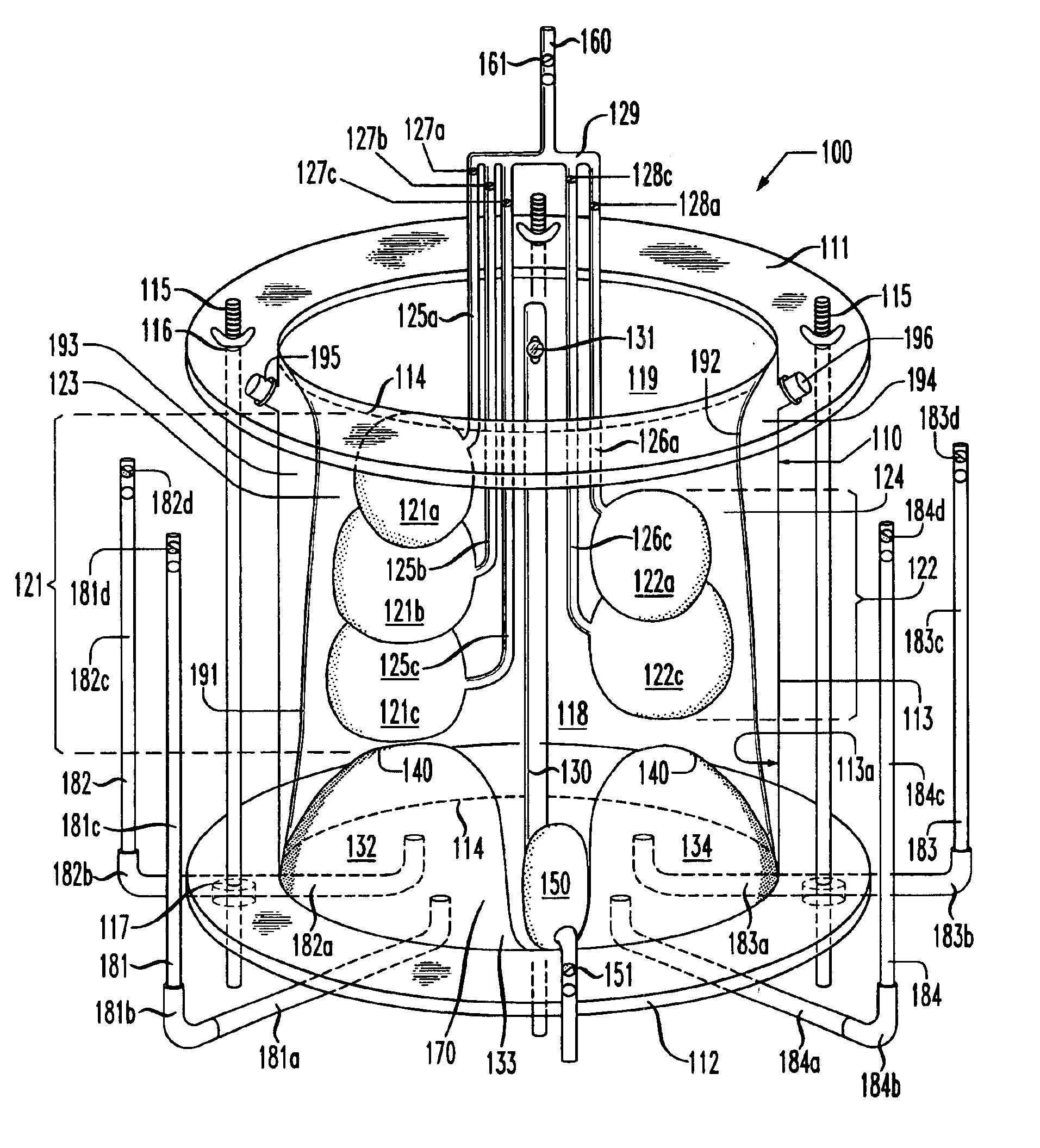
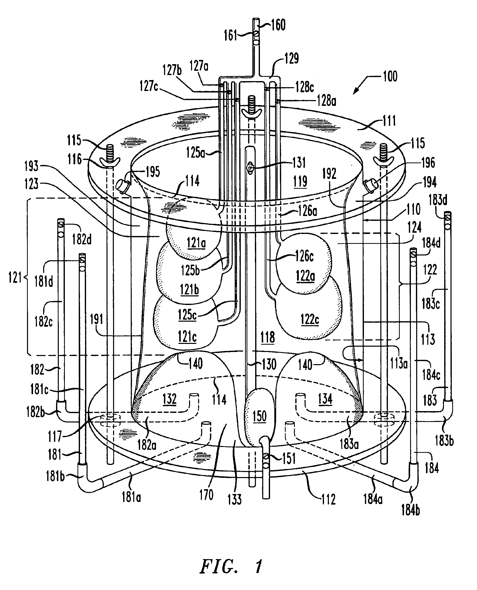
Referring initially to FIG. 1, illustrated is a front elevation, partial sectional view of a lung simulator 100 constructed according to the principles of the present invention. The lung simulator 100, in the particular embodiment shown, comprises a simulated human thoracic cavity 110, right and left simulated human lungs 121, 122, respectively, a simulated mediastinum 130, a simulated human diaphragm 140, a simulated human heart 150, a simulated human trachea 160, a simulated lower abdominal cavity 170, a plurality of manometers 181-184, and right and left flexible membranes 191, 192, respectively, that define right and left simulated pleural spaces 193, 194, respectively. In a preferred embodiment, the simulated human thoracic cavity 110 is a substantially-rigid, fluid-tight, translucent housing 110 constructed primarily of sheet polymethylmetracrylate. In a preferred embodiment, the housing 110 is transparent so as to make changes internal to the housing 110 readily visible. Of c...


PUM


Abstract

The present invention provides a lung simulator comprising a substantially-rigid, fluid-tight, translucent housing simulating a human thoracic cavity and at least one flexible air-tight bag simulating a lung having a plurality of simulated lung lobes, and a corresponding plurality of valves, each of the plurality of valves coupled to a one of the plurality of simulated lung lobes and configured to simulate varying degrees of fluid flow resistance. In a preferred embodiment, the substantially-rigid, fluid-tight, transparent housing has isolated simulated left and right thoracic cavities therein and the at least one flexible air-tight bag is located within one of the simulated thoracic cavities. The present invention further provides a method of manufacturing a lung simulator.

Description

TECHNICAL FIELD OF THE INVENTIONThe present invention is directed, in general, to a lung simulator and, more specifically, to a lung simulator that may be used as an educational tool and as a tool to set parameters of mechanical ventilators for specific pathophysiologies.BACKGROUND OF THE INVENTIONWhile lung simulators are known in the art, they are typically limited to devices suitable for cardiopulmonary resuscitation (CPR) training such as: U.S. Pat. Nos. 3,276,147 to de Bella, U.S. Pat. No. 4,001,950 to Blumensaadt, and U.S. Pat. No. 3,049,811 to Ruben. These patents illustrate the effect of mouth-to-mouth resuscitation upon one or more inflatable bags having some resistance to inflation and related operating equipment. Likewise, U.S. Pat. No. 3,274,705 to Breakspear illustrates a plurality of bags connected to inflate and deflate responsive to mount-to-mouth-resuscitation. None of these devices are suitable to demonstrate the interaction of the organs resident within a human th...

Claims


Application Information

Patent Timeline
Patent Type & Authority Patents(United States)
IPC IPC(8): G09B23/00G09B23/32G09B23/28A62B27/00
CPCG09B23/32G09B23/288A62B27/00
Inventor ESTETTER, ROBERT H.HOLLAND, JR., THURMAN D.HIGGINS, JASON T.
Owner ESTETTER ROBERT H
Why Eureka
Try Eureka