Method and apparatus for chest drainage

a chest cavity and chest technology, applied in the field of general surgery, thoracic surgery, trauma and critical care, can solve the problems of compromising drainage, internal organ damage, and iatrogenic trauma risk of patients, so as to reduce steps, minimize trauma, and reduce errors

Inactive Publication Date: 2008-02-05
BREZNOCK EUGENE M +1
View PDF11 Cites 38 Cited by
  • Summary
  • Abstract
  • Description
  • Claims
  • Application Information

AI Technical Summary

Benefits of technology

[0010]The cannula of the present invention includes an internal, semi-automatic valving mechanism, which allows for fewer steps and minimizes the chance of leaving the chest tube open to atmosphere when drainage is completed. The cannula of the present invention also comprises an external movable fixation device to prevent inadvertently pushing the cannula too far into the patient. The minimally invasive placement method of the present invention is beneficial in not only the emergency setting but also in the hospital setting by reducing the chance of iatrogenic injury to the patient.
[0021]The combination of minimally invasive placement and reduced steps to operate the chest drainage tube will benefit patients and medical practitioners by reducing errors, minimizing trauma, increasing ease of use, and improving patient outcomes.

Problems solved by technology

With any invasive surgical procedure, there exists a risk of iatrogenic trauma to the patient.
Significant training is required to safely perform these procedures and this training may not have been completed by emergency personnel who are the first line of treatment for many patients experiencing trauma.
There may also be a problem with a chest tube being pushed too far into the patient, resulting in kinking, compromised drainage and potential iatrogenic damage to internal organs.

Method used


Image

  • Method and apparatus for chest drainage
  • Method and apparatus for chest drainage
  • Method and apparatus for chest drainage

Examples


Embodiment Construction

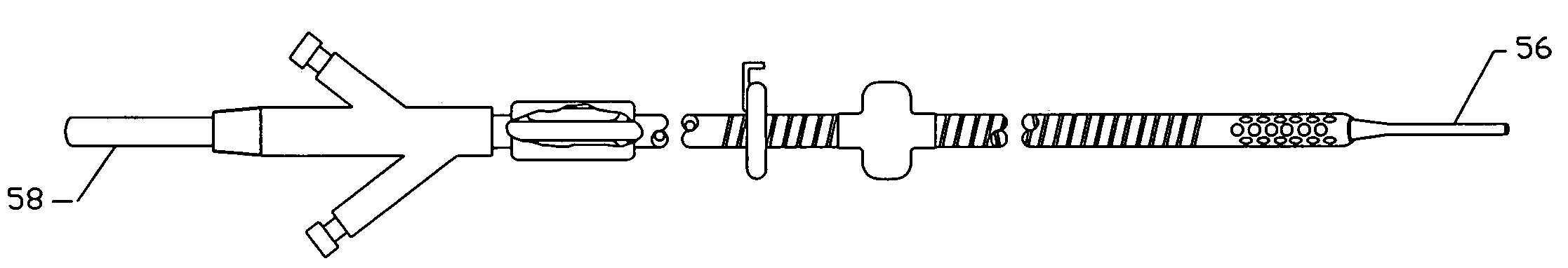
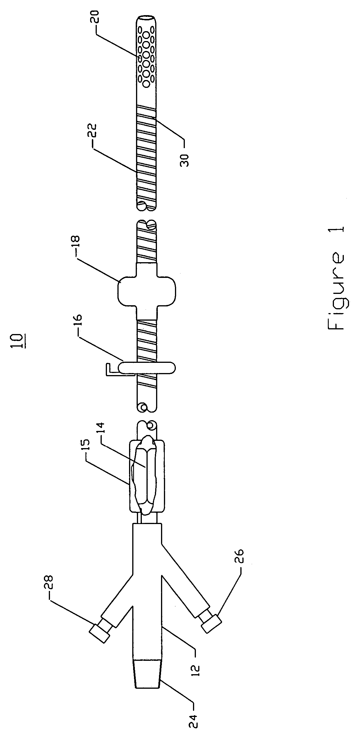
[0031]FIG. 1 illustrates a cannula, tube or catheter 10 of the present invention. The catheter 10 comprises a manifold or hub 12, a bidirectional or two-way valve or seal 14. an extracorporeal fixation device 16, an intracorporeal fixation device 18, a plurality of drainage holes 20, and a length of multi-lumen tubing 22. In addition, the catheter 10 optionally comprises a valve housing 15. The manifold 12 comprises a drainage adapter or fitting 24, a valve-enabling adapter or fitting 26, and an intracorporeal fixation-enabling adapter or fitting 28. In this preferred embodiment, the intracorporeal fixation device 18 is a balloon, and the intracorporeal fixation-enabling adapter 28 is a balloon inflation adapter or fitting. The multi-lumen tubing preferably comprises a stiffening wire 30.

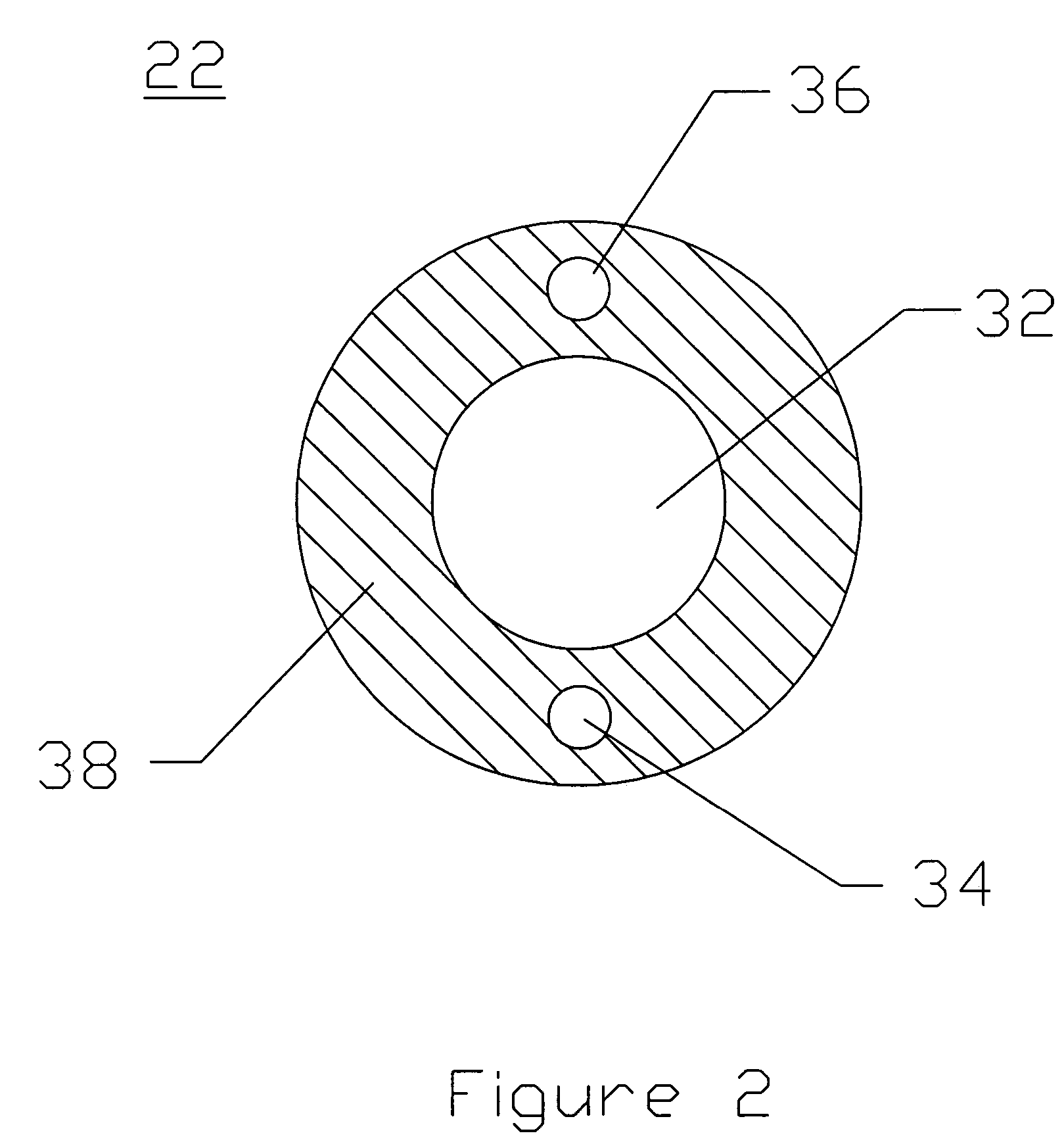
[0032]FIG. 2 illustrates a cross-section of the multi-lumen tubing 22. The multi-lumen tubing 22 comprises a drainage lumen 32, a valve enabling lumen 34, an intracorporeal fixation-enabling lumen 3...


PUM


Abstract

The present invention describes a device for placement in the thoracic cavity of a patient. The device is a cannula, tube or catheter for chest drainage. The device serves as a conduit for drainage of excessive fluid or air buildup in the chest to a receptacle outside the body. The device also serves to prevent influx of fluid or air into the chest cavity, thus preventing pneumothorax or infection. The device incorporates systems for anchoring the chest drainage cannula to the chest and for steering the chest drainage cannula into the thoracic cavity.

Description

PRIORITY CLAIM[0001]This application is a continuation of U.S. application Ser. No. 09 / 908,316, filed on Jul. 17, 2001, now U.S. Pat. No. 6,638,253.FIELD OF THE INVENTION[0002]The field of this invention is general surgery, thoracic surgery, trauma and critical care.BACKGROUND OF THE INVENTION[0003]Chest drainage tubes are used following thoracic surgery, chest trauma or to treat certain medical conditions. The purpose of a chest tube is to remove buildup of excessive body fluids, contaminants or air from the thoracic cavity. The presence of an opening into the chest or thorax, created with or without a cannula will cause pneumothorax (collapsed lung). Negative pressure in the chest cavity is created by the chest muscles and diaphragm in order to cause lung expansion and resulting inspiration of a breath. Therefore, a hole in the chest will equalize pressure and prevent critical lung function, i.e. lung insufflation. Any cannula placed into a patient's chest cavity for drainage must...

Claims


Application Information

Patent Timeline
Patent Type & Authority Patents(United States)
IPC IPC(8): A61M1/00A61M27/00A61M37/00A61M35/00
CPCA61M27/00A61M35/00A61M2210/1039
Inventor BREZNOCK, EUGENE M.LENKER, JAY A.
Owner BREZNOCK EUGENE M
Why Eureka
Try Eureka