
Saddles for pedal-operated machines

a pedal-operated machine and saddle technology, applied in the saddle field of saddles for bicycles, tricycles, exercise bicycles, etc., can solve the problems of rider's physical or other medical problems, rider's insecurity, etc., and achieve the effect of not restricting the movement of the leg and better accommodating the weigh

Inactive Publication Date: 2005-04-05
COX BRIAN ANTHONY
View PDF20 Cites 5 Cited by
  • Summary
  • Abstract
  • Description
  • Claims
  • Application Information

AI Technical Summary

Benefits of technology

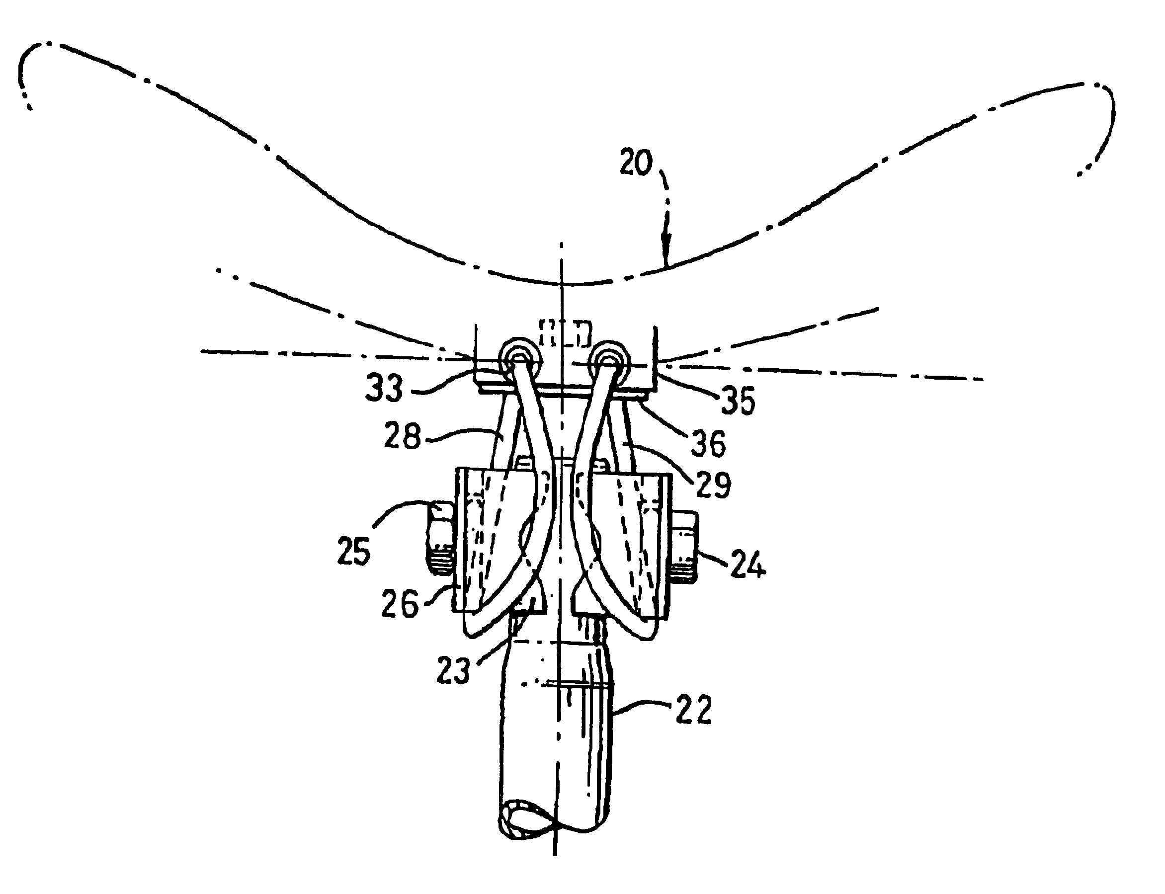
When a rider is pedalling a cycle, his hips perform a kind of rolling action with the pelvis rocking from side to side. The saddle of the present invention allows that pelvic action to occur in a natural and unrestricted way, assisting the application of the maximum driving force to the down-going pedal of the cycle. This is because the saddle may rock in such a way that the side of the saddle on the same side of the cycle as the down-going pedal moves downwardly with respect to the other side of the saddle, so not restricting the movement of the leg on the down-going pedal. The opposite side of the saddle rises slightly so better accommodating the weight of the rider on that buttock on that side of the saddle. Then, as the pedals rotate and the other pedal starts its down-going travel, the saddle may rock in the other sense, so freeing for easy movement the leg driving that other pedal.

Problems solved by technology

Unfortunately, a rider may suffer physical problems or other medical consequences from prolonged or excessive cycling on a conventional saddle of this kind, due to the pressure exerted by the horn on the rider's crotch.
However, all of these saddles suffer from various disadvantages including quite often a feeling of insecurity for the rider.

Method used


Image

  • Saddles for pedal-operated machines
  • Saddles for pedal-operated machines
  • Saddles for pedal-operated machines

Examples


Embodiment Construction

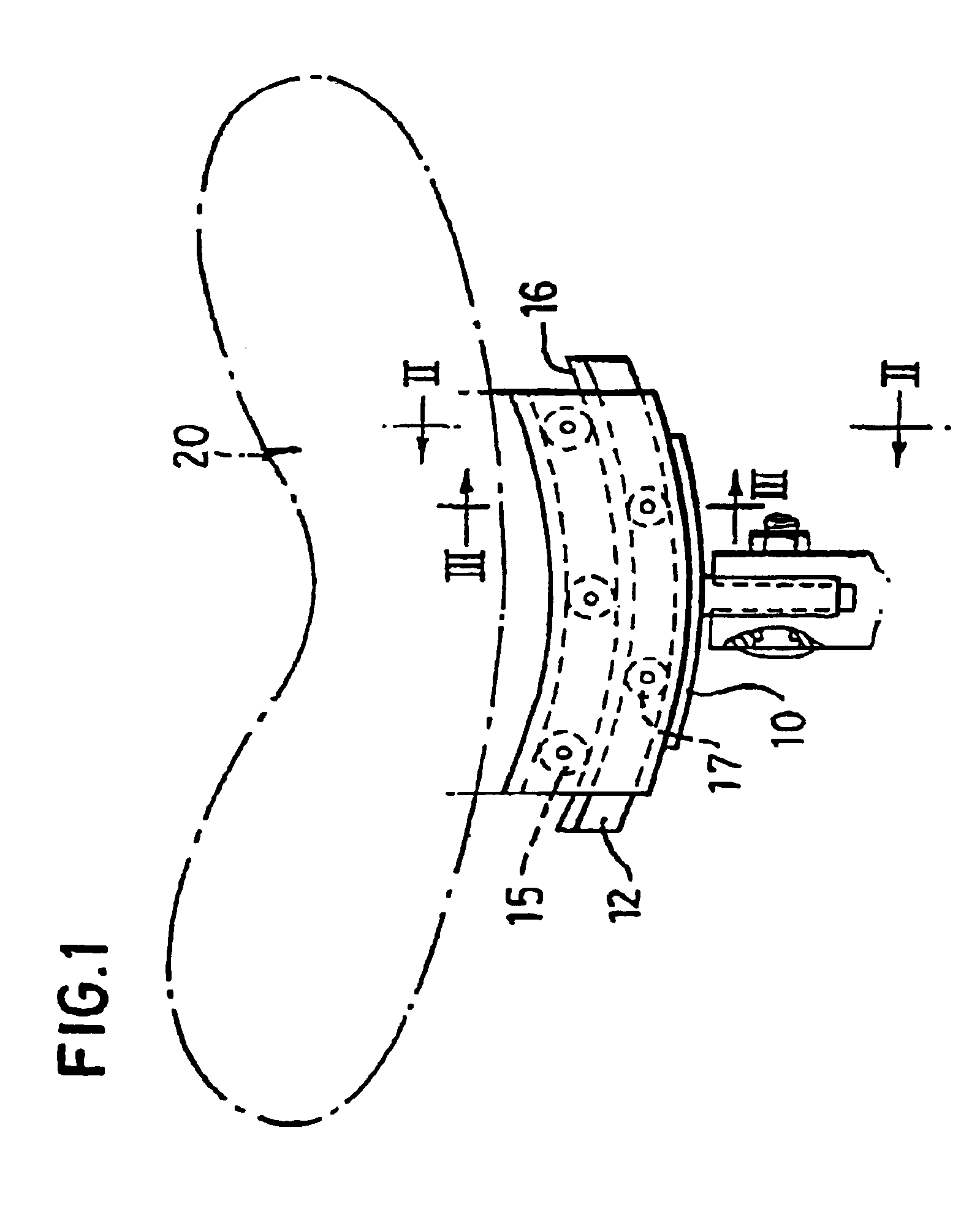
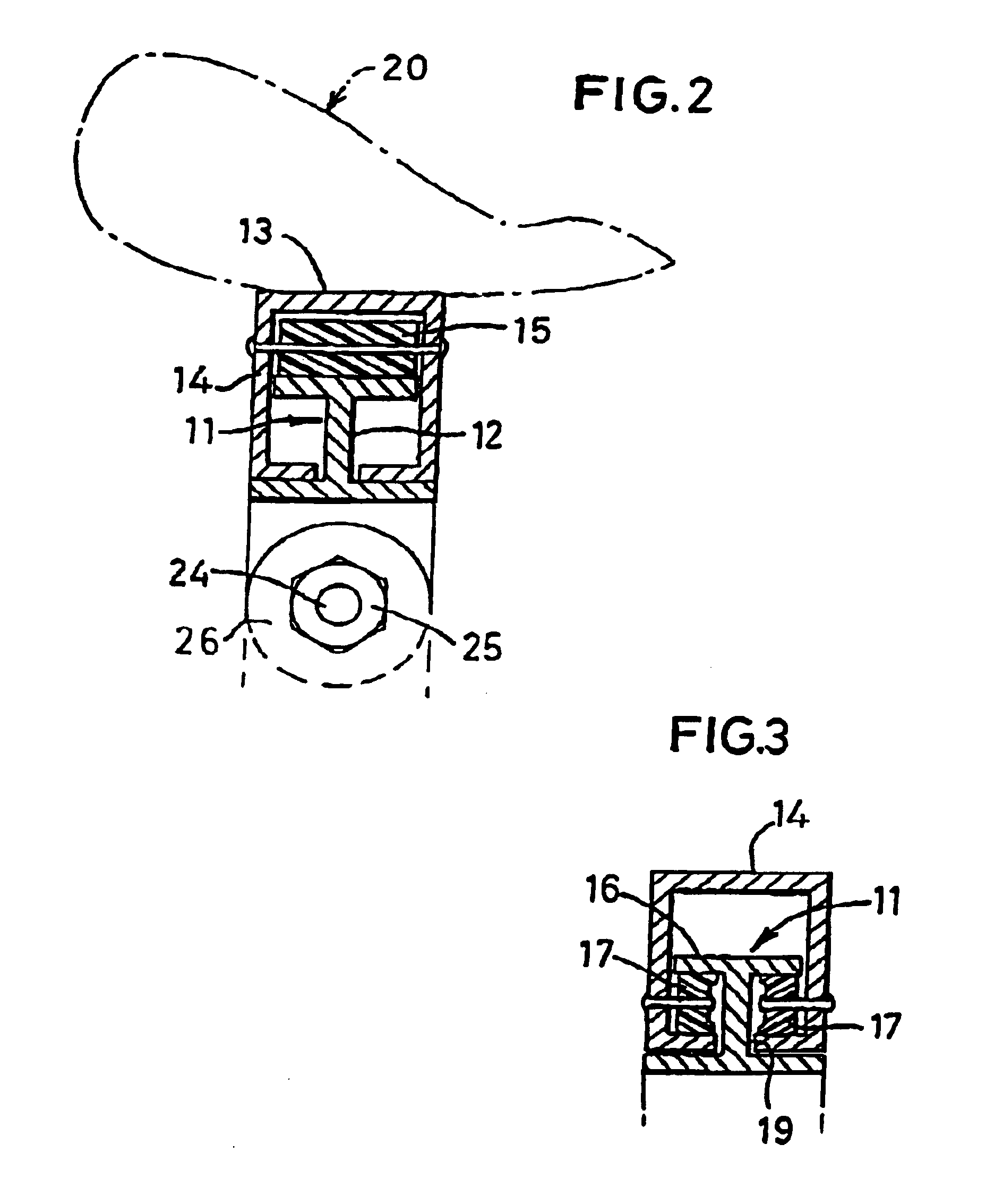
In one embodiment of this invention, the saddle is mounted for movement laterally of a cycle and when performing that lateral movement, the saddle simultaneously undergoes a rotational motion about a centre of curvature above the upper surface of the saddle. In an alternative embodiment, the saddle is supported in such a way that it performs a pivoting action having a centre of curvature above the upper surface of the saddle. In this case, though the saddle may move laterally to a small extent, the primary motion is one of pivoting about the centre of curvature above the upper surface.

Though the rocking motion has been described as having an effective axis above the upper surface of the saddle, the rocking motion could be a complex rocking motion and not a simple part-circular motion having a fixed centre of curvature. Thus, the effective centre of curvature for the rocking motion when of a complex form may itself be a locus, of arcuate shape.

The mounting arrangement advantageously ...


PUM


Abstract

A saddle for a bicycle, tricycle, exercise cycle or the like has a mounting arrangement which permits the saddle to rock from side to side as a rider pedals the cycle. The rocking motion has an effective centre above the surface of the saddle and the saddle is resiliently biased so as to return to its central position when the cycle is not being ridden.

Description

BACKGROUND OF THE INVENTION(I) Field of the InventionThis invention relates to a saddle for a pedal-operated machine, and in particular—but not exclusively—to a saddle for a bicycle, tricycle, exercise bicycle or the like.The saddle of this invention is primarily intended for use with a bicycle, which will hereinafter be referred to simply as a “cycle”. Though the invention will hereinafter be described exclusively with reference to cycles, it is to be understood that the saddle is suitable for use on a wide variety of pedal-operated machines including those mentioned above and the term “cycle” is not to be understood as limiting the invention to bicycles.(II) Description of the Related ArtThe function of a cycle saddle is to support the greater part of the rider's weight and at the same time to restrain the rider's seat slipping off the saddle while leaving his or her legs free to rotate the pedals. A conventional cycle saddle has a rearward, relatively broad platform on which the ...

Claims


Application Information

Patent Timeline
Patent Type & Authority Patents(United States)
IPC IPC(8): B62J1/00B62J1/08
CPCB62J1/08B62J1/00
Inventor COX, BRIAN ANTHONY
Owner COX BRIAN ANTHONY
Learn More