
Headrest device for a vehicle seat, and a vehicle seat including such a device

a headrest and vehicle seat technology, applied in the field of vehicle seat headrest devices, can solve the problems of increasing the overall size of the seat, and affecting the use of the seat, so as to protect the seat user effectively, the effect of easy transportation and easy mounting

Inactive Publication Date: 2005-04-05
FAURECIA
View PDF14 Cites 25 Cited by
  • Summary
  • Abstract
  • Description
  • Claims
  • Application Information

AI Technical Summary

Benefits of technology

The invention is a headrest device for a vehicle seat that includes a stop device that can hold the headrest in a retracted position. The stop device can be moved from an inactive position to an active position to prevent the headrest from being moved beyond its low abutment position. The headrest can be raised from its retracted position to a low abutment position while the stop device is in its active position. The stop device is actuated by an actuator device that moves it from its inactive position to its active position. The headrest device also includes an adjustment mechanism that allows the headrest to move vertically between a high position and a low abutment position. The stop device can be engaged with a pin and a stop notch to prevent the pin from sliding again. The actuator device can be a second stop member that drives the stop device from its inactive position to its active position. The headrest is mounted to slide on the pin between the high position and the low abutment position. The invention provides a vehicle seat with a seat back equipped with a headrest device.

Problems solved by technology

Headrests of that type suffer, in particular, from the drawback of increasing the overall size of the seat while said seat is being transported and / or while it is being mounted in the vehicle, when the seat is transported and / or mounted with the headrest mounted on the back of the seat.
That increase in overall size complicates and increases the cost of transporting and / or mounting the seat, and it can even be incompatible with mounting the seat in certain small vehicles.

Method used


Image

  • Headrest device for a vehicle seat, and a vehicle seat including such a device
  • Headrest device for a vehicle seat, and a vehicle seat including such a device
  • Headrest device for a vehicle seat, and a vehicle seat including such a device

Examples


Embodiment Construction

In the various figures, like references designate elements that are identical or similar.

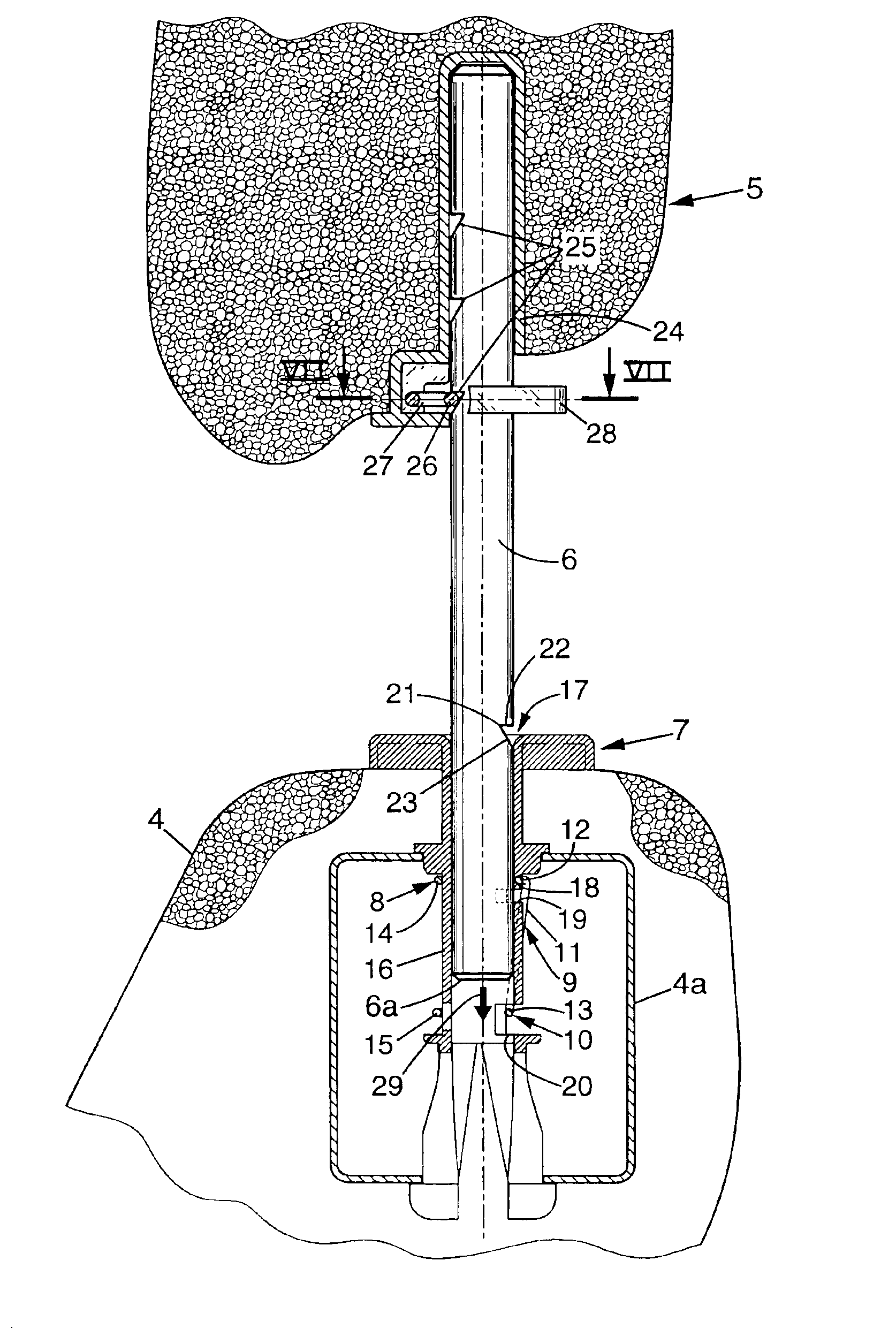
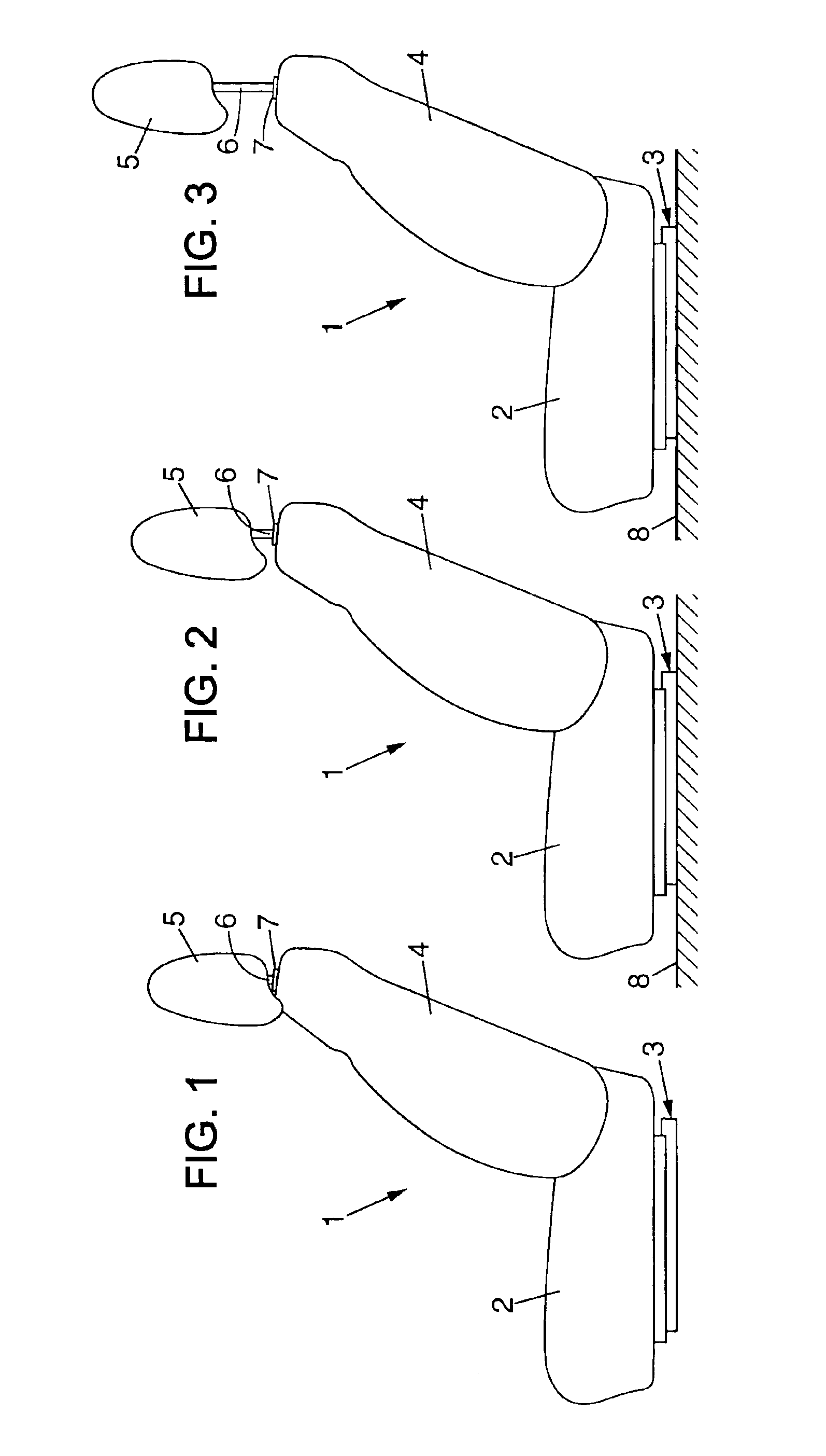
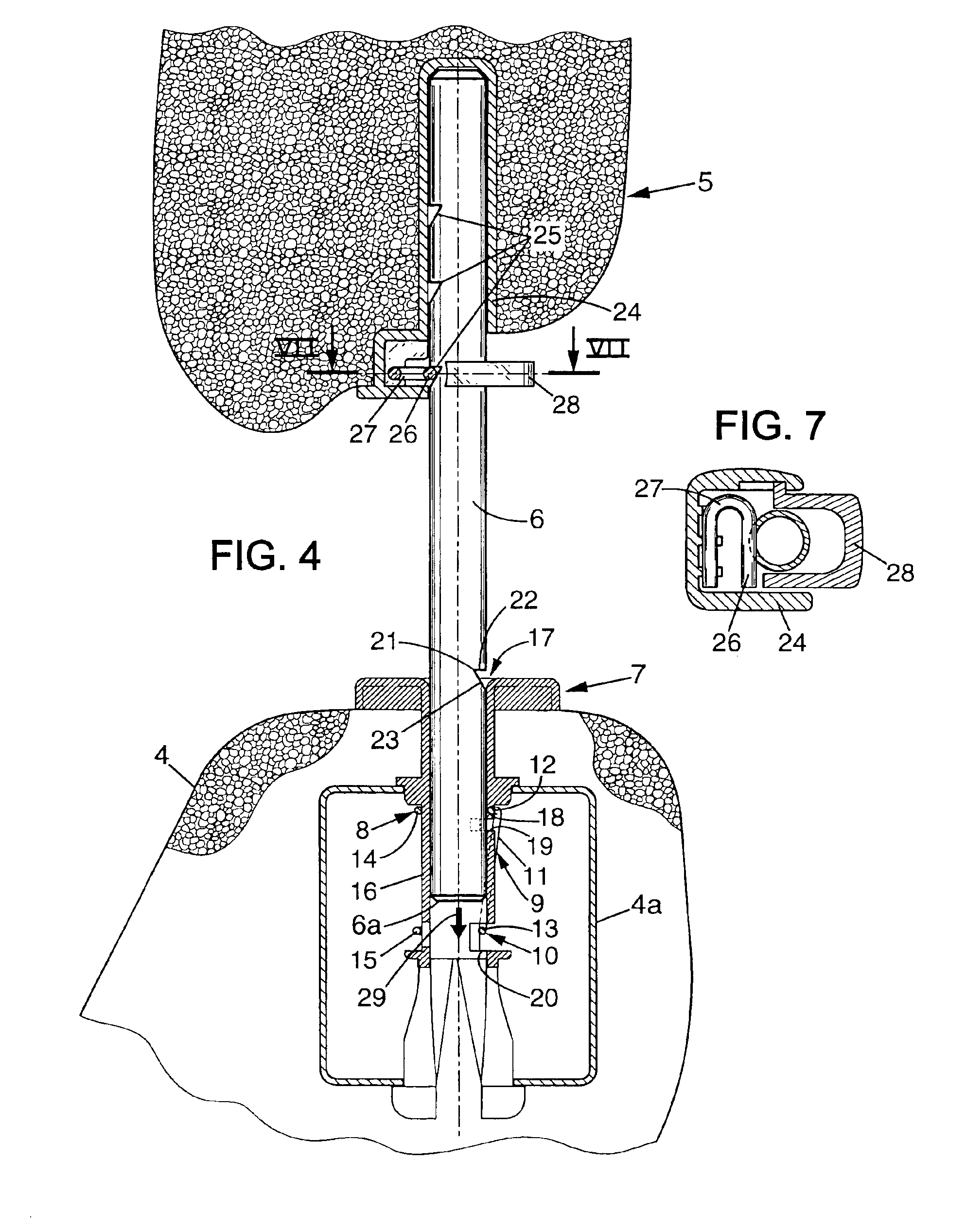
FIG. 1 shows a motor vehicle seat 1 before it is mounted in the vehicle. The seat 1 has a seat proper 2 which is designed to be fixed to the floor of the vehicle, e.g. via a runner 3 adapted to enable the overall position of the seat to be adjusted longitudinally. The seat also has a seat back 4 on the top of which a headrest 5 is mounted, the headrest being connected to the seat back via two substantially vertical pins 6 mounted, for example, in respective ones of two supports, such as bushings 7 that are secured to the seat back 4 (only one of the pins 6 and only one of the bushings 7 are visible in FIG. 1).

The headrest 5 is initially in a retracted position in which said headrest comes into direct contact with the top portion of the seat back 4. This retracted position enables the seat 1 to be very compact, and thus makes it possible for the seat 1 to be mounted in the vehicle relatively easi...


PUM


Abstract

A headrest device for a vehicle seat, the headrest device including a stop device that is mounted to move between an active position adapted to prevent the headrest from being moved downwards beyond a low abutment position, and an inactive position adapted to enable the headrest to be moved downwards beyond its low abutment position into a retracted position. An actuator device is adapted to move the stop device from its inactive position to its active position while the headrest is being moved into its retracted position.

Description

The present invention relates to headrest devices for vehicle seats, and to vehicle seats including such devices.More particularly, the invention relates to a headrest device for a vehicle seat, the headrest device comprising: a headrest carried by at least one support designed to be secured to the back of the seat.BACKGROUND OF THE INVENTIONDocument FR-A-2 551 810 describes an example of such a headrest.Headrests of that type suffer, in particular, from the drawback of increasing the overall size of the seat while said seat is being transported and / or while it is being mounted in the vehicle, when the seat is transported and / or mounted with the headrest mounted on the back of the seat. That increase in overall size complicates and increases the cost of transporting and / or mounting the seat, and it can even be incompatible with mounting the seat in certain small vehicles.OBJECTS AND SUMMARY OF THE INVENTIONAn object of the invention is to mitigate that drawback.To this end, in the i...

Claims


Application Information

Patent Timeline
Patent Type & Authority Patents(United States)
IPC IPC(8): B60N2/48A47C7/38
CPCB60N2/4814B60N2/4817B60N2002/4894B60N2/815B60N2/894B60N2/818
Inventor TERRAND, NICOLASKLUKOWSKY, SLAVOMIRHUGUET, GUILLAUME
Owner FAURECIA
Learn More