Fixing device for fixing an autofocus module to a mirror box of an SLR camera

a technology for fixing devices and mirror boxes, which is applied in the direction of mountings, instruments, focusing aids, etc., can solve problems such as difficulty in adjusting the position of af modules

Active Publication Date: 2005-04-05
RICOH IMAGING COMPANY
View PDF9 Cites 6 Cited by
  • Summary
  • Abstract
  • Description
  • Claims
  • Application Information

AI Technical Summary

Benefits of technology

The AF module optical system can further include a reflecting mirror and a second condenser lens. The light bundle, which is reflected by the sub-mirror after passing through the half mirror portion, firstly passes through the condenser

Problems solved by technology

However, if the deviation is great, it is difficult to adjust the position of the AF modu

Method used


Image

  • Fixing device for fixing an autofocus module to a mirror box of an SLR camera
  • Fixing device for fixing an autofocus module to a mirror box of an SLR camera
  • Fixing device for fixing an autofocus module to a mirror box of an SLR camera

Examples


Embodiment Construction

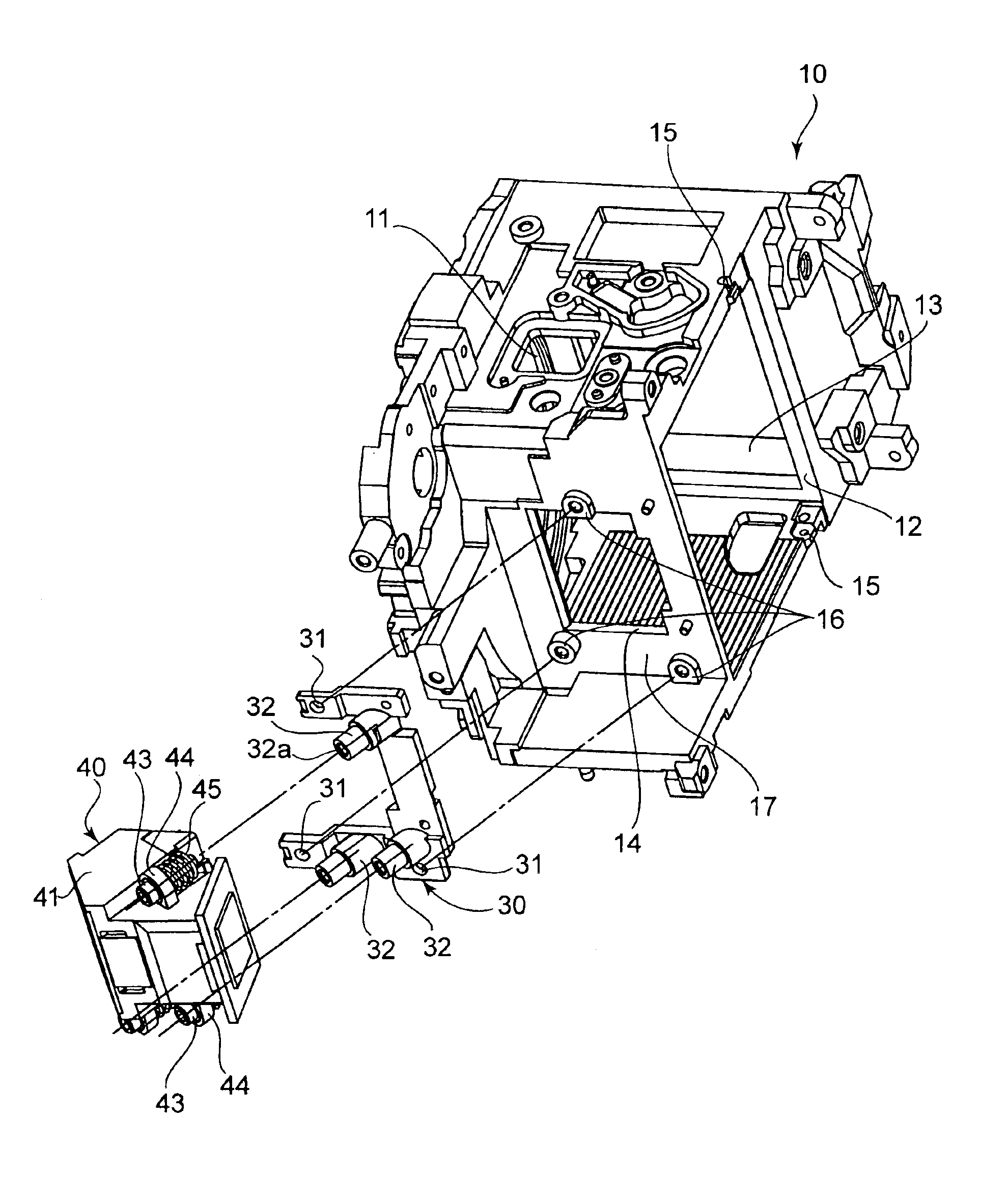
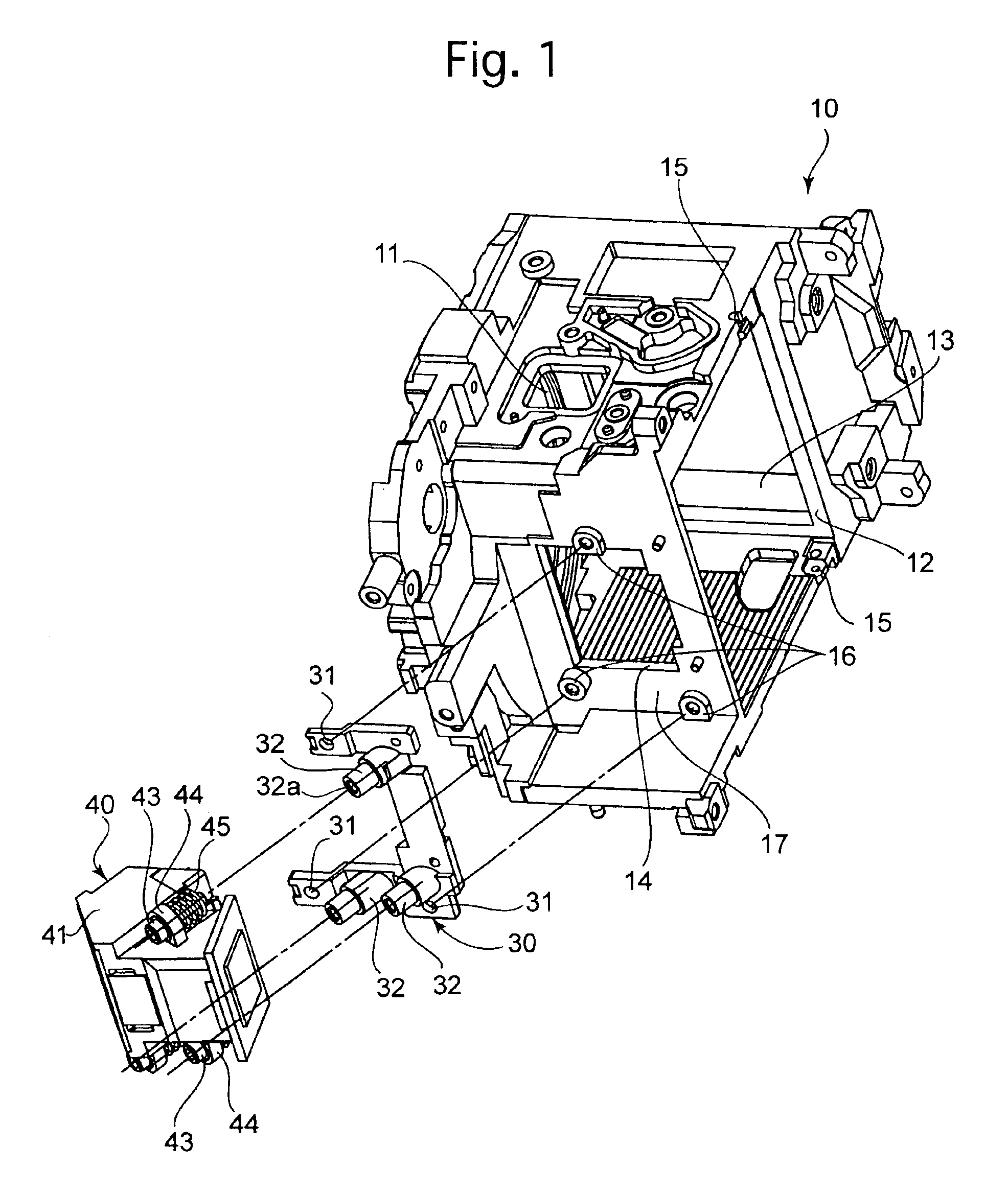
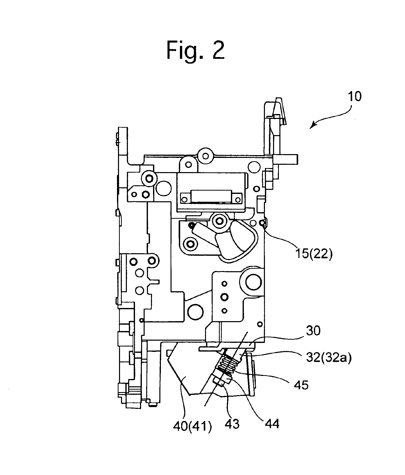
As shown in FIGS. 1 and 2, a mirror box 10 of an SLR camera is in the shape of a substantially rectangular prism. The mirror box 10 is provided on the front thereof with a lens mount (circular aperture) 11 to which an interchangeable photographing lens (not shown) is detachably attached. The mirror box 10 is provided on the rear end thereof with a rectangular photographing aperture 12 for a focal plane shutter (not shown). The mirror box 10 is provided on top thereof with a rectangular aperture 13 for a viewfinder optical system (not shown). The mirror box 10 is provided on the side walls thereof with a pair of bearing holes 15 in which opposite ends of a horizontal pin (pivot) 22 of a quick-return mirror 20 (see FIG. 3) are fitted, respectively. The mirror box 10 is provided with a bottom wall 17 which has a bottom opening 14 for an AF (autofocus) module 40. The mirror box 10 is provided, on an underside thereof around the bottom opening 14, with three fixing holes 16 for fixing an...


PUM


Abstract

A fixing device for fixing an autofocus module to a mirror box of an SLR camera having a quick-return mirror accommodated in the mirror box, wherein the quick-return mirror has a half mirror portion so that a light bundle of an object which is passed through the half mirror portion is reflected by a sub-mirror to be incident on the autofocus module. The fixing device includes an adjustment bracket which is provided separately from the mirror box, the adjustment bracket is fixed to an underside of the mirror box, and the auto focus module is fixed to the adjustment bracket.

Description

BACKGROUND OF THE INVENTION1. Field of the InventionThe present invention relates to a fixing device for fixing an autofocus module to a mirror box of an SLR camera in which a quick-return mirror is accommodated.2. Description of the Related ArtIn typical SLR cameras having an autofocus system, a part of the quick-return mirror (main mirror) is formed as a half mirror portion while a sub-mirror is held by the quick-return mirror to be positioned behind the half mirror portion so that a light bundle of an object which is passed through the half mirror portion (hereinafter referred to as “object light bundle for autofocusing”) is reflected downwards by the sub-mirror to be incident on an AF (autofocus) module which includes a CCD line sensor and other optical elements. Conventionally, the angle of the sub-mirror with respect to the quick-return mirror is determined so that the object light bundle for autofocus is reflected downwards by the sub-mirror in a direction substantially ortho...

Claims


Application Information

Patent Timeline
IPC IPC(8): G03B19/12G03B13/36G02B7/28
CPCG03B19/12
Inventor MORISHITA, SHIGERU
Owner RICOH IMAGING COMPANY
Why Eureka
Try Eureka