Device comprising a case and an applicator

a technology of case and applicator, which is applied in the direction of applications, packaging goods, brushes, etc., can solve the problems of applicator threads being moved past the studs of the case in an undesirable fashion, and achieve the effect of easy automation and convenient manufacture of the devi

Inactive Publication Date: 2005-04-05
LOREAL SA
View PDF10 Cites 31 Cited by
  • Summary
  • Abstract
  • Description
  • Claims
  • Application Information

AI Technical Summary

Benefits of technology

The receptacle may be engaged in a housing of the transmission member, the housing presenting an opening that can be brought into register with the side opening of the case to enable substance to be taken. In such an embodiment, the transmission member may be of substantially the same length as the case, thereby making it easier to handle.
The slots may present outwardly-diverging openings, said openings following one another circumferentially in such a manner that a user returning the applicator into the case can easily engage the studs in the slots without needing initially to take care to position the applicator angularly with precision relative to the case. The transmission member may be put into place in the case by being inserted axially therein. The slots may define tongues between one another, said tongues possibly being adapted to snap-fasten on the case, in particular on the above-mentioned annular shoulder, when the transmission member is fully inserted into the case.
Manufacture of the device is made easier when the case and the applicator can be presented to an assembly station attached to each other, and the operation of inserting the receptacle containing the substance into the case, in particular along the axis of the case, is an operation that is relatively easy to automate.

Problems solved by technology

Such turning, however, can cause the studs of the applicator to be moved past the threads of the case in an undesirable fashion.

Method used


Image

  • Device comprising a case and an applicator
  • Device comprising a case and an applicator
  • Device comprising a case and an applicator

Examples


Embodiment Construction

Throughout the present text, including in the claims, the term “comprising a” should be understood as being synonymous with “comprising at least one” unless the contrary is specified.

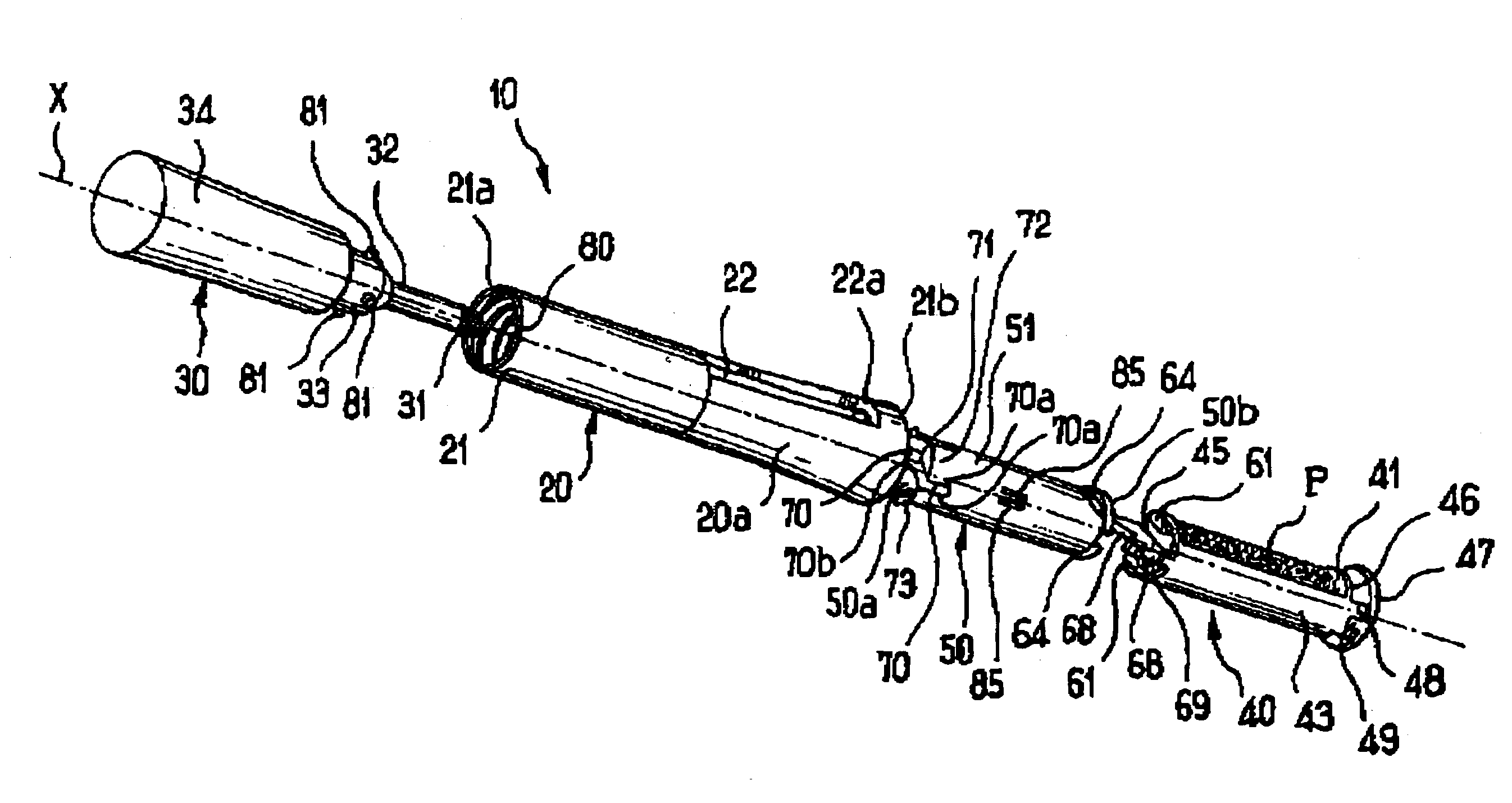
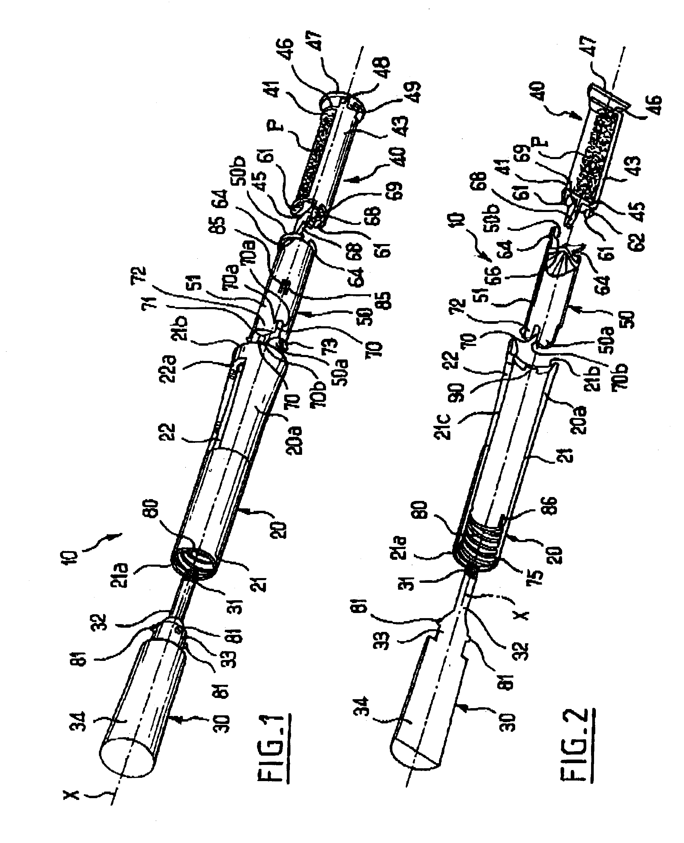
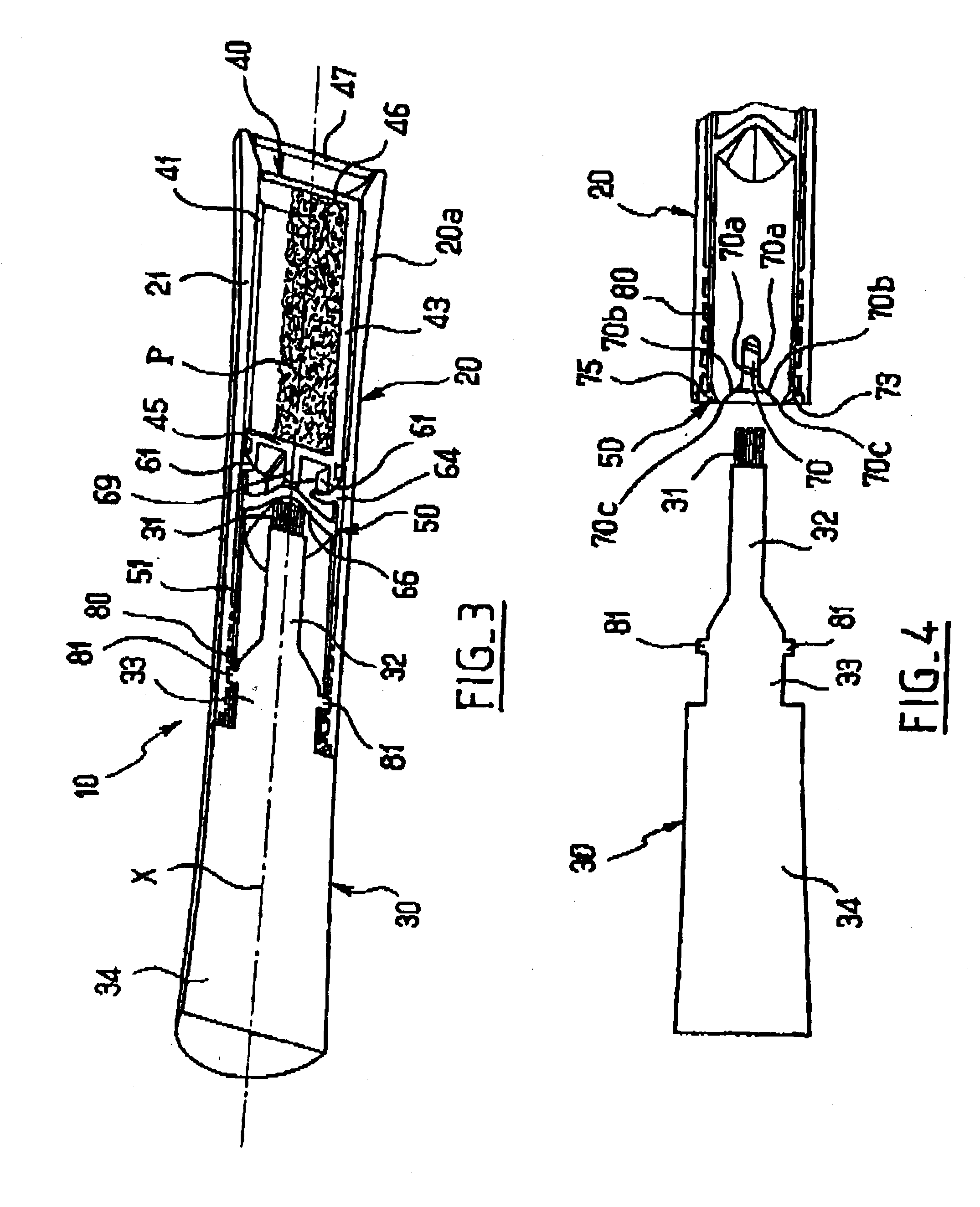
The applicator device 10 shown in FIGS. 1 to 4 comprises a case 20 and an applicator 30, which applicator 30 can be secured to the case 20 when not in use. In the embodiment shown, the case 20 is elongate in shape along a longitudinal axis X and comprises a tubular body 21 open at two opposite ends, openings 21a and 21b. The body 21 is made by injecting a rigid and opaque thermoplastic material, for example. The case 20 also has a side opening 22, which opening 22 is substantially rectangular in shape in the embodiment shown. The opening 22 has a short side in the range 0.5 centimeters (cm) to 1.5 cm, and a long side in the range 3 cm to 5 cm, for example. In the embodiment shown, the opening 22 is made in a portion 20a, which occupies a little more than half of the body 21, beside the opening 21b, for ...


PUM


Abstract

A packaging and applicator device is disclosed. The device comprising a compartment for receiving a receptacle containing a substance; a applicator capable of being releasably fixed to the device; a first opening through which the applicator can take the substance; a shutter associated with the first opening and capable of taking a closed position and an opened position; a transmission member capable of being driven in displacement by the applicator to move the shutter into at least one of the open and closed positions; and a second opening distinct from the first and through which the receptacle can be inserted in said compartment, by being moved relative to the transmission member.

Description

CROSS REFERENCE TO RELATED APPLICATIONSThe present application claims the benefit of FR 01 / 16,786 filed Dec. 21, 2001, the disclosure of which is hereby incorporated by reference.BACKGROUND OF THE INVENTION(i) Field of the InventionThe present invention relates to devices for applying at least one substance, in particular devices comprising a case having an axis, an applicator that is separable from the case, and a receptacle containing the substance, said receptacle being received at least in part inside the case, the case having at least one side opening through which the substance can be taken by means of the applicator.(ii) Description of Related ArtEuropean patent application EP A21 118 286 provides examples of devices in which the substance to be applied is contained in a cup which can be put into place in a housing for receiving it when the applicator is separated from the case. In FIG. 28, there is described an embodiment including a transmission member, a case and an applic...

Claims


Application Information

Patent Timeline
Patent Type & Authority Patents(United States)
IPC IPC(8): A45D33/16A45D33/00A45D40/26A45D34/00B65D83/00
CPCA45D40/265A45D33/16
Inventor DUQUEROIE, FLORENTALBISETTI, NICOLAS
Owner LOREAL SA
Why Eureka
Try Eureka