Method of removing assist features utilized to improve process latitude

Inactive Publication Date: 2005-04-05
ASML NETHERLANDS BV
View PDF11 Cites 27 Cited by
  • Summary
  • Abstract
  • Description
  • Claims
  • Application Information

AI Technical Summary

Benefits of technology

[0024]Accordingly, it is an object of the present invention to provide a method which allows for the use of the AFs and

Problems solved by technology

One of the primary problems caused by such proximity effects is an undesirable variation in feature CDs.
However, recently, more aggressive illumination schemes such as annular illumination and multipole illumination have been implemented as a means of improving resolution and known OPC techniques have not always had the desired effects with such illumination schemes.
Furthermore, when printing features having s

Method used


Image

  • Method of removing assist features utilized to improve process latitude
  • Method of removing assist features utilized to improve process latitude
  • Method of removing assist features utilized to improve process latitude

Examples


Example

DETAILED DESCRIPTION OF THE DRAWINGS

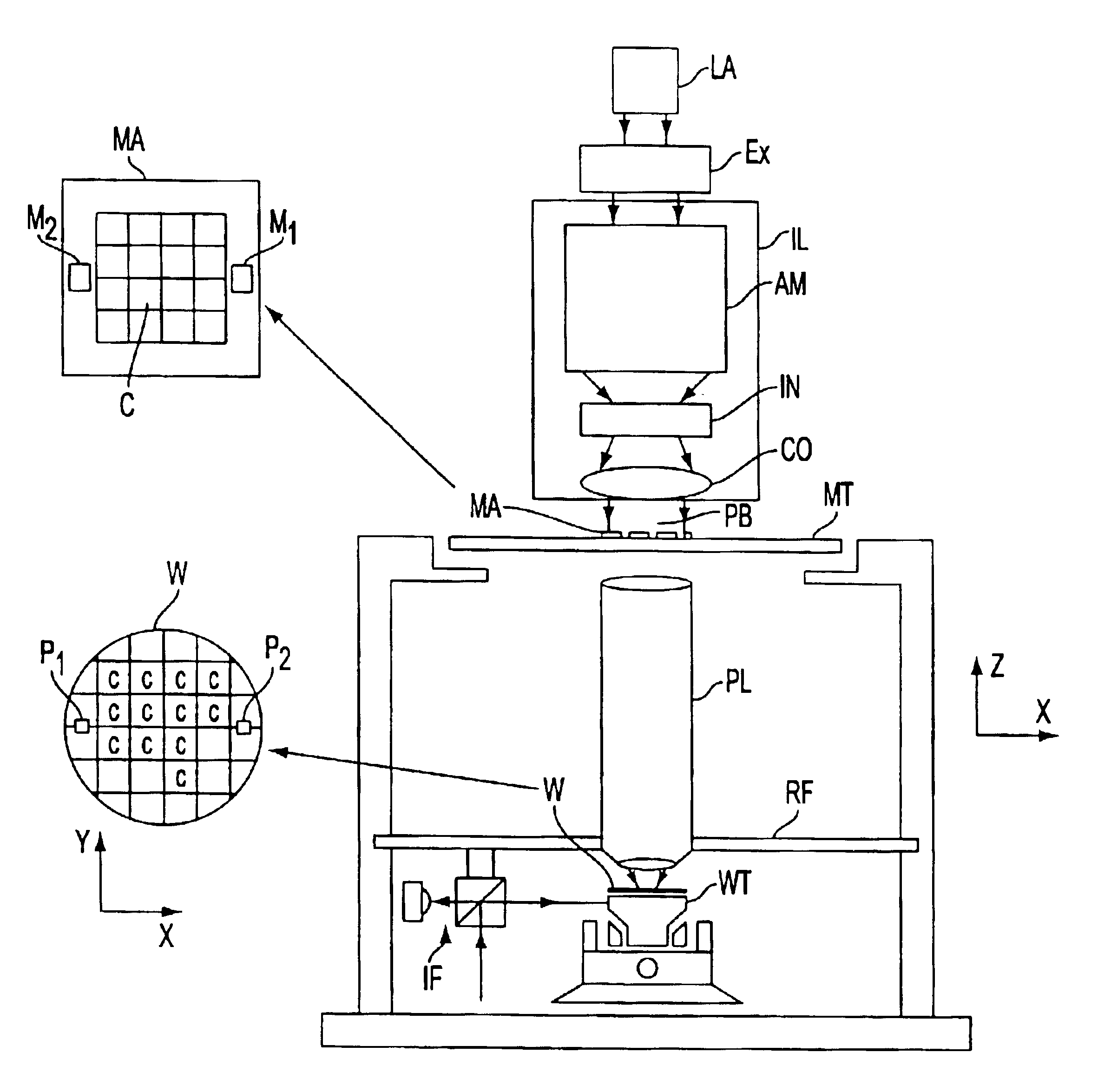
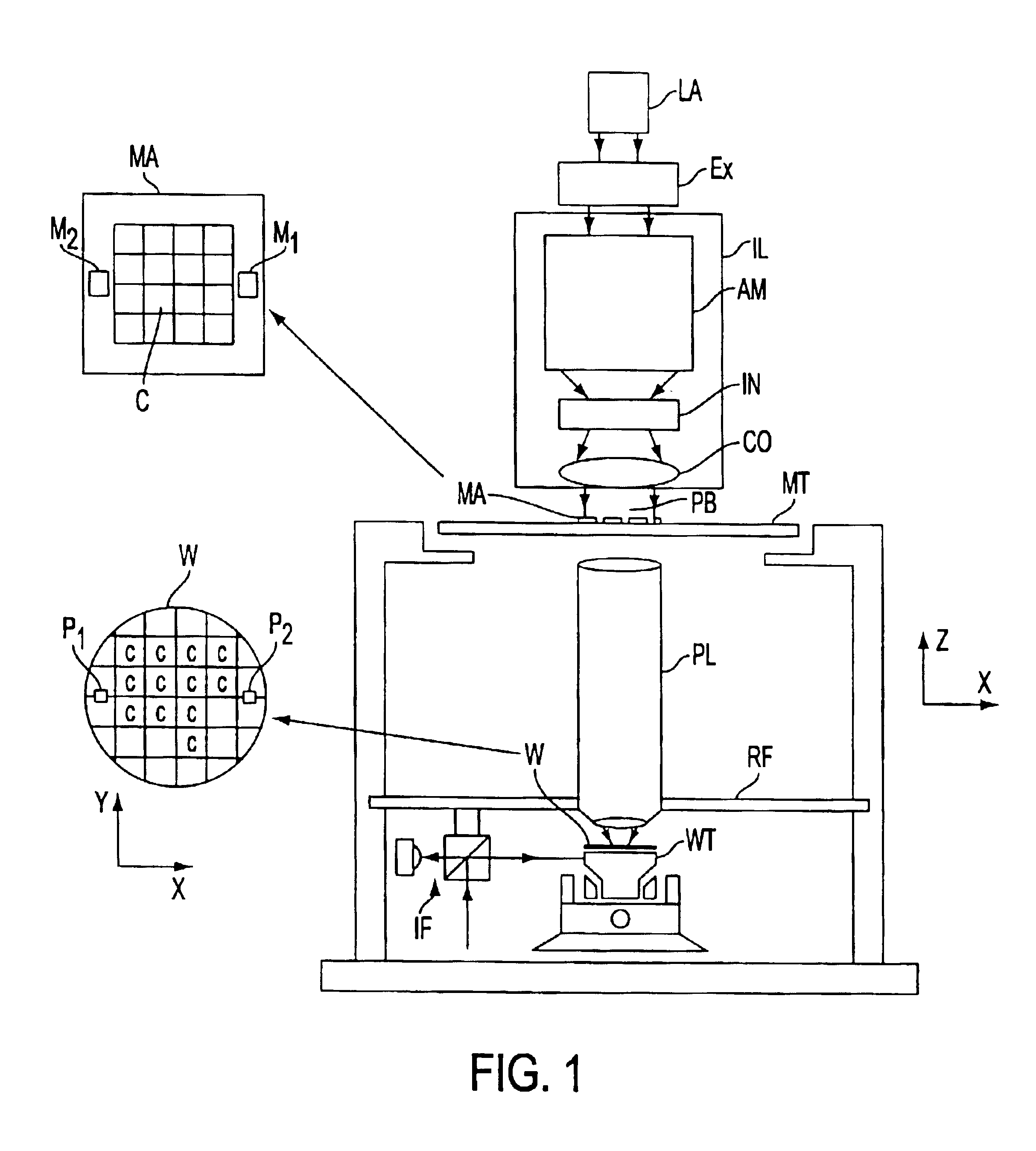
[0042]FIG. 1 schematically depicts an exemplary lithographic projection apparatus suitable for use with a AF removal process of the present invention. The apparatus comprises:

[0043]a radiation system Ex, IL, for supplying a projection beam PB of radiation. In this particular case, the radiation system also comprises a radiation source LA;

[0044]a first object table (mask table) MT provided with a mask holder for holding a mask MA (e.g. a reticle), and connected to first positioning means for accurately positioning the mask with respect to item PL;

[0045]a second object table (substrate table) WT provided with a substrate holder for holding a substrate W (e.g. a resist-coated silicon wafer), and connected to second positioning means for accurately positioning the substrate with respect to item PL;[0046]a projection system (“lens”) PL (e.g. a refractive, catoptric or catadioptric optical system) for imaging an irradiated portion of the mask MA onto a ...


PUM


Abstract

A method of transferring a lithographic pattern onto a substrate by use of a lithographic apparatus. The method includes the steps of: (1) defining features to be printed on the substrate; (2) determining which of the features require assist features to be disposed adjacent thereto in order for the features to be printed within defined resolution limits; (3) generating a mask containing the features to be printed and the assist features; (4) performing a first illumination process so as to print the features on the substrate, the first illumination process resulting in the partial printing of the assist features on the substrate; and (5) performing a second illumination process so as to reduce the amount of the assist features printed on the substrate; the second illumination process entails the step of performing a quadrapole illumination.

Description

[0002]This application claims the benefit of provisional application No. 60 / 333,503, filed Nov. 28, 2001.[0003]The present invention relates to photolithography and more particularly to optical proximity correction methods used during the development of photolithography masks for use in lithographic apparatus comprising:[0004]a radiation system for supplying a projection beam of radiation;[0005]a support structure for supporting patterning means, the patterning means serving to pattern the projection beam according to a desired pattern;[0006]a substrate table for holding a substrate; and[0007]a projection system for projecting the patterned beam onto a target portion of the substrate.[0008]The term “patterning means” as herein employed should be broadly interpreted as referring to means that can be used to endow an incoming radiation beam with a patterned cross-section, corresponding to a pattern that is to be created in a target portion of the substrate; the term “light valve” can ...

Claims


Application Information

Patent Timeline
IPC IPC(8): G02F1/1335G03F7/20G03F1/14G03F1/00H01L21/027
CPCG03F1/144G03F7/70466G03F7/70441G03F7/70125G03F1/36G03F1/70H01L21/027
Inventor EURLINGS, MARKUS FRANCISCUS ANTONIUSCHEN, JANG FUNGHSU, DUAN-FU STEPHEN
Owner ASML NETHERLANDS BV
Why Eureka
Try Eureka