Adjustable planar antenna

Inactive Publication Date: 2005-04-05
CANTOR FITZGERALD SECURITIES
View PDF15 Cites 104 Cited by
  • Summary
  • Abstract
  • Description
  • Claims
  • Application Information

AI Technical Summary

Benefits of technology

An advantage of the invention is that the adjusting of a PIFA-type planar antenna is performed by means of small additive components, which do not presume changes in the antenna's basic structure. Thereupon the antenna's size does not change and the extra cost of the adjustability is relatively low. Another advantage of the invention is that the effe

Problems solved by technology

However, a drawback of the reducing of said distance is that the bandwidth(s) of the antenna are becoming smaller.
Then, as a mobile terminal is designed to function according to different systems having frequency ranges relatively close to each other, it becomes more difficult or impossible without special arrangements to cover said frequency ranges used by more than one radio system.
Correspondingly, securing the function that conforms to specifications in both transmitting and receiving bands of a single system can become more difficult.
A drawback of this solution is that the effect of a single switch is minimal, and therefore many switches are nee

Method used


Image

  • Adjustable planar antenna
  • Adjustable planar antenna
  • Adjustable planar antenna

Examples


Embodiment Construction

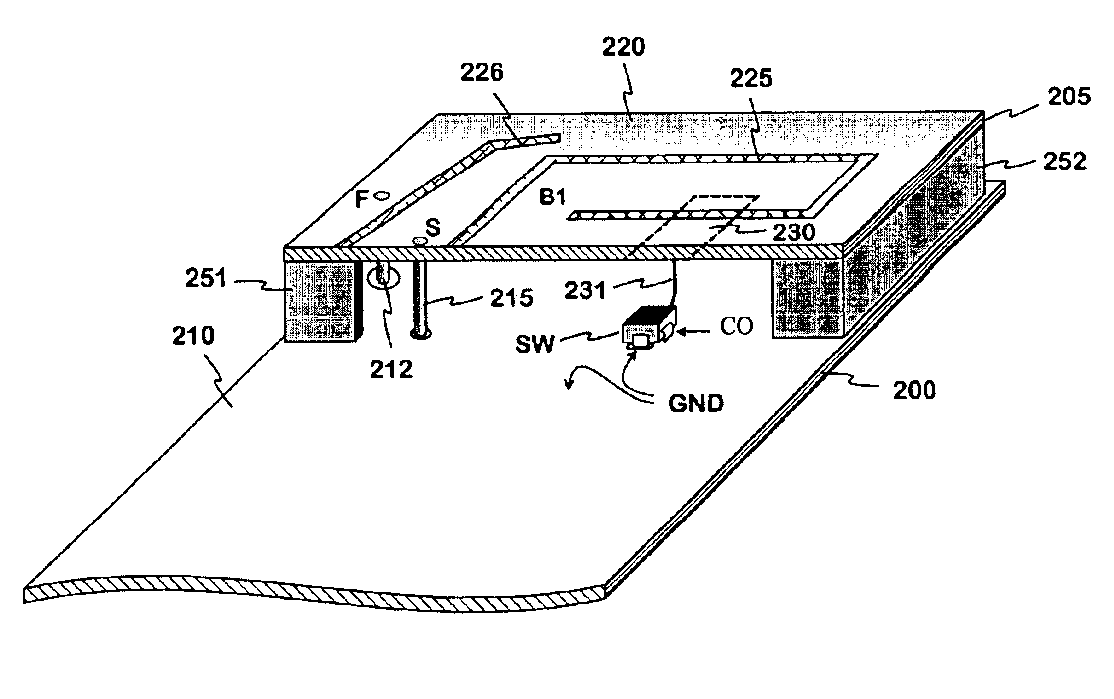
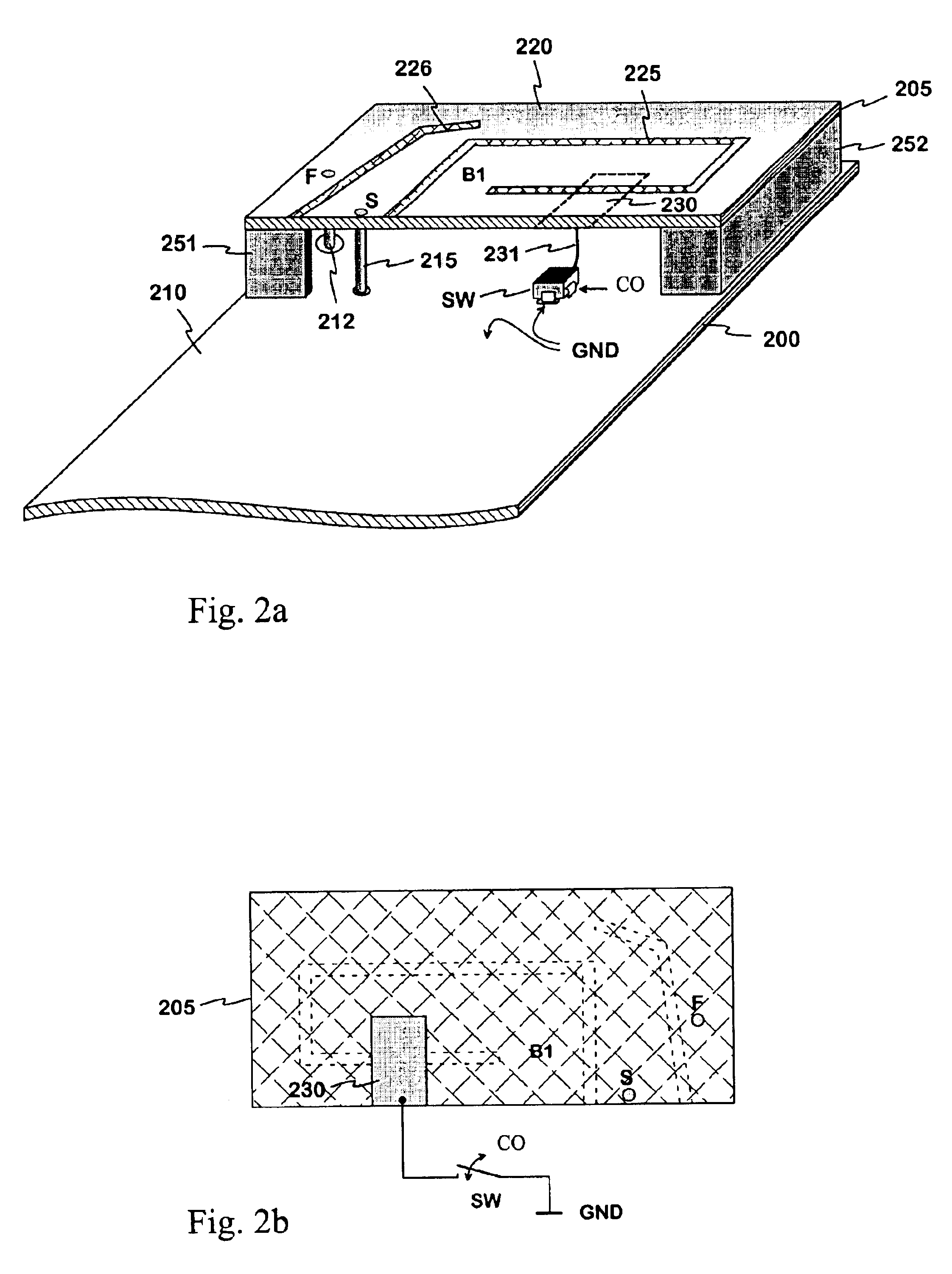
FIGS. 2a, b show an example of a adjustable planar antenna according to the invention. In FIG. 2a there is seen a part of a circuit board 200 of a radio device, the antenna of which is in question. The upper surface of the radio device's circuit board is mostly conductive functioning as the ground plane 210 of the planar antenna and at the same time as the signal ground GND. Above the one end of the circuit board 200, at a height determined by dielectric pieces 251 and 252, there is a rectangular dielectric plate 205. On the upper surface of this plate there is the antenna's radiating plane 220. To the radiating plane is connected the antenna's feed conductor 212 at the feed point F and the short conductor 215 at the short point S. The short conductor connects the radiating plane galvanically to the ground plane to match the antenna's impedance. The antenna then is PIFA-type. In the radiating plane there is a first slot 225 starting from the one longer edge of the plate, on the oute...


PUM


Abstract

An adjustable planar antenna especially applicable to mobile terminals, and to a radio device provided with that kind of antenna. The basic structure of the antenna is PIFA. On a surface of a dielectric part (205) there is placed a strip conductor (230) so that this has a significant electromagnetic coupling to the radiating plane (220). The strip conductor can be connected by a switch (SW) to the ground plane. When the switch is closed, the electric length of the radiating plane is changed, measured from the short point (S). In which case also the antenna's resonance frequency is changed. The change depends on the place and the size of the strip conductor. In the case of a multi-band antenna the strip conductor can be placed so that it has a remarkable electromagnetic coupling to one or more radiating elements (B1, 226). The adjusting of planar antenna is performed by means of small additive components, which do not presume changes in the antenna's basic structure and do not enlarge the antenna.

Description

The invention relates to an adjustable planar antenna especially applicable in mobile terminals. The invention further relates to a radio device employing that kind of antenna.BACKGROUND OF THE INVENTIONIn portable radio devices, mobile terminals in particular, the antenna is preferably placed inside the covers of the device for convenience. The internal antenna of a small device is usually of planar-type, because satisfactory electric characteristics are then most easily achieved for the antenna. The planar antenna comprises a radiating plane and a ground plane parallel therewith. As mobile terminals are becoming smaller thickness-wise, too, the distance between the radiating plane and the ground plane of a planar antenna should be as short as possible. However, a drawback of the reducing of said distance is that the bandwidth(s) of the antenna are becoming smaller. Then, as a mobile terminal is designed to function according to different systems having frequency ranges relatively ...

Claims


Application Information

Patent Timeline
IPC IPC(8): H01Q9/04H01Q21/30H01Q1/24H01Q5/10
CPCH01Q1/243H01Q21/30H01Q9/0442H01Q9/0421
Inventor MILOSAVLJEVIC, ZLATOLJUB
Owner CANTOR FITZGERALD SECURITIES
Why Eureka
Try Eureka