
Surge suppressor enclosure and fusing system

a technology of suppressor and enclosure, which is applied in the direction of emergency protective circuit arrangement, electrical equipment, circuit arrangement, etc., can solve the problems of limiting the ability of the mov to temporarily shorten transient voltage surges, excessive a.c. current drawn from the power line, extensive smoke, etc., to prevent current flow and prevent current flow

Inactive Publication Date: 2005-04-05
RAYCAP INC
View PDF5 Cites 51 Cited by
  • Summary
  • Abstract
  • Description
  • Claims
  • Application Information

AI Technical Summary

Benefits of technology

A surge suppressor includes a surge suppression device. A novel current limiting fuse design prevents current flow when the surge suppression device fails. A thermal fusing device is configured to prevent current flow when excessive heat is generated in the surge suppression device. A novel enclosure is used for containing the surge suppression device, over current fuse and thermal fuse.

Problems solved by technology

When MOVs fail they can create a short circuit that draws excessive A.C. current from the power line.
Until the fuse or circuit breaker opens, a large current is conducted through the circuit possibly causing catastrophic results such as extensive smoke, mechanical damage and fire.
However smaller fuses severely limit the ability of the MOV to temporarily short transient voltage surges.
If a voltage spike or power surge is in excess of the combined energy handling capability of the multiple MOVs, one or more of the fused MOVs blow.
Other MOVs and electrical equipment in the enclosure may be damaged by an explosion or fire that happens during the power surge condition.
If the explosion is severe enough, the smoke and explosion from the power surge event may destroy the plastic enclosure and other electrical equipment located next to the enclosure.
For example, the electrical surge event may damage electrical equipment in a load center or transfer switch containing the surge suppressor, resulting in large monetary losses.

Method used


Image

  • Surge suppressor enclosure and fusing system
  • Surge suppressor enclosure and fusing system
  • Surge suppressor enclosure and fusing system

Examples


Embodiment Construction

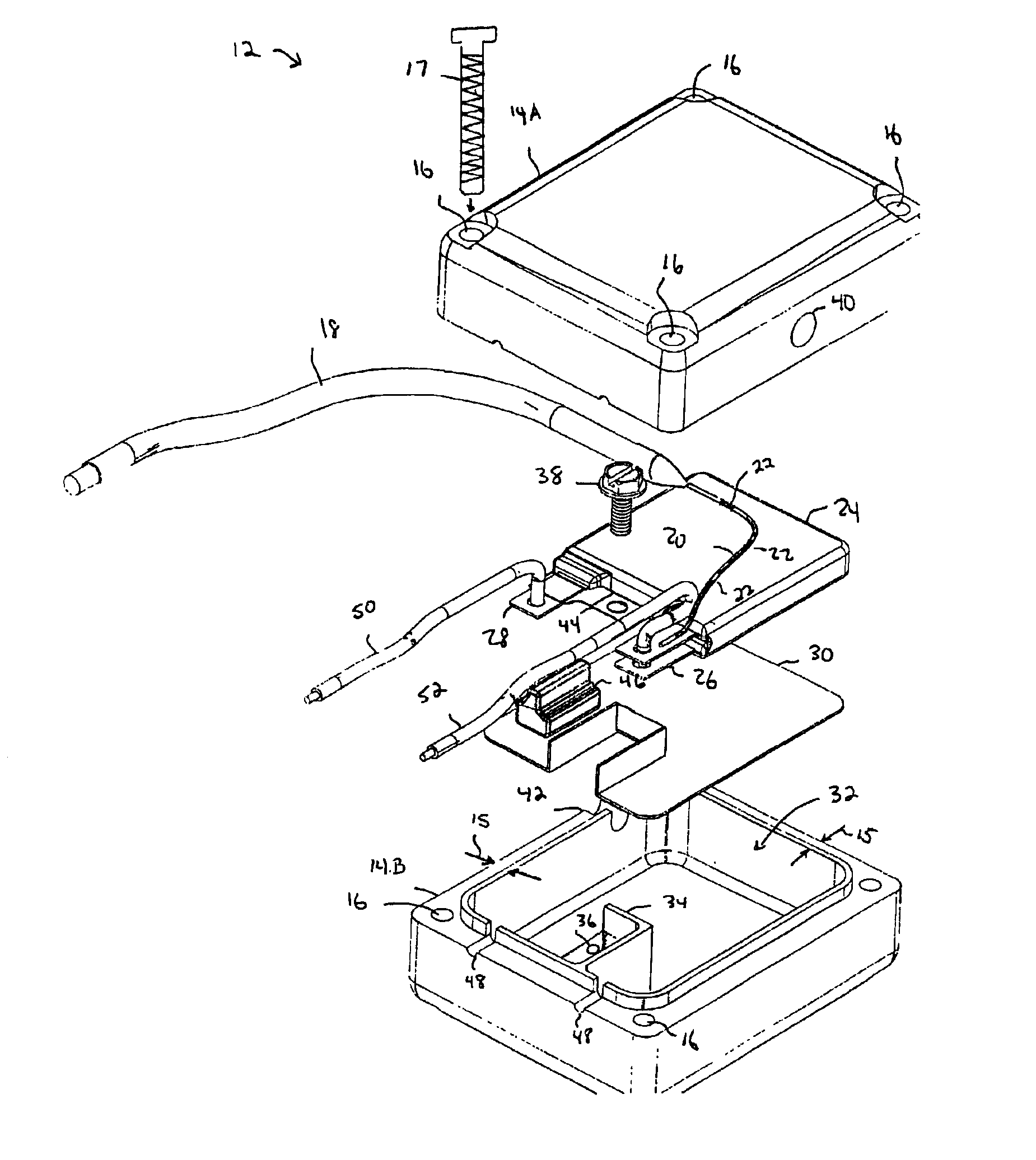
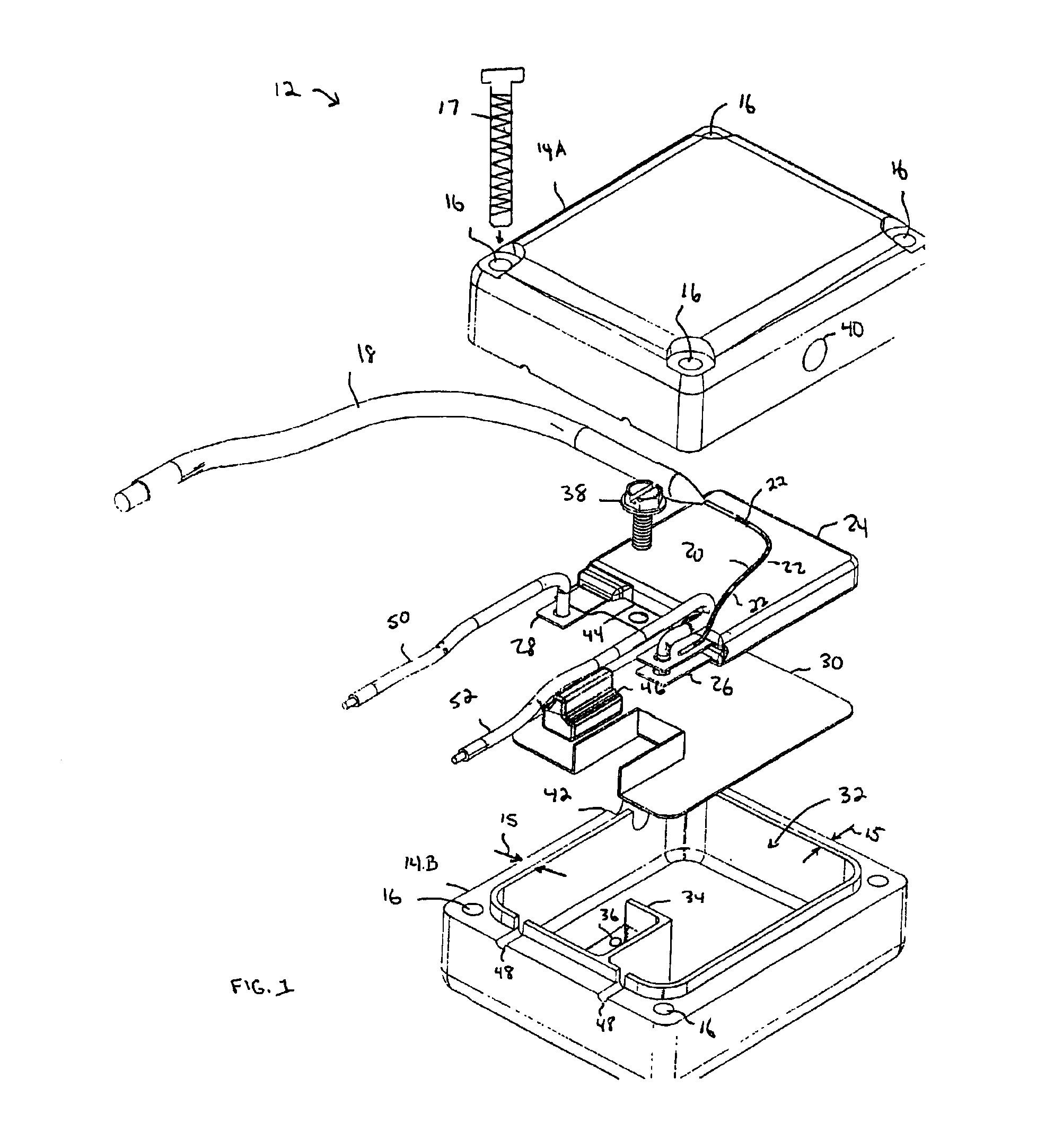
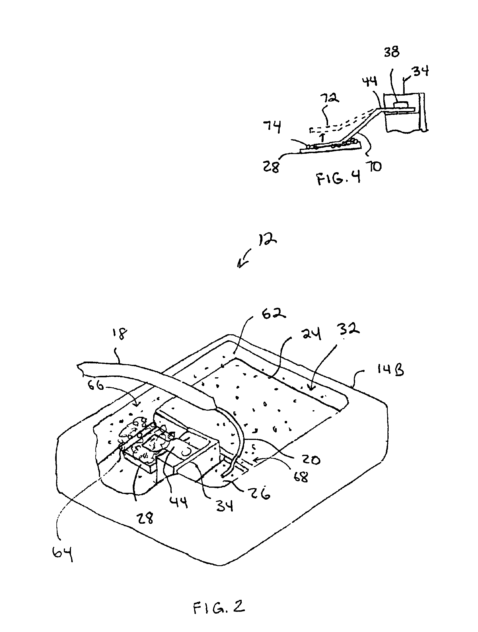
FIG. 1 shows a surge suppressor 12 that includes a Metal Oxide Varister (MOV) 24, a current limiting fuse 20, and a thermal fuse 44 all contained inside a metal enclosure 14. The surge suppressor 12 is a module that can be incorporated into other power protection equipment. The MOV 24 in one embodiment is an off the shelf device that is known to those skilled in the art.

The enclosure 14 includes an upper piece 14A and a lower piece 14B. The two enclosure pieces 14A and 14B form an internal cavity 32 that retains the MOV 24. In one example, the enclosure 14 is around 2¾ inches wide, 2¾ inches in height and around 1½ inches in depth. The walls 15 of the enclosure 14 in one example are around one quarter inch thick and are made from aluminum or some other conductive metal material.

Encasing the MOV 24 in metallic enclosure 14 isolates arcing and other destructive events caused by an electrical surge condition of MOV failure. For example, the strength of enclosure 14 isolates explosions,...


PUM


Abstract

A surge suppressor includes a surge suppression device. A novel current limiting fuse design prevents current flow when the surge suppression device fails. A thermal fusing device is configured to prevent current flow when excessive heat is generated in the surge suppression device. A novel enclosure is used for containing the surge suppression device, over current fuse and thermal fuse.The foregoing and other objects, features and advantages of the invention will become more readily apparent from the following detailed description of a preferred embodiment of the invention which proceeds with reference to the accompanying drawings.

Description

BACKGROUNDTransient Voltage Surge Suppression (TVSS) devices use Metal Oxide Varistors (MOVs). A MOV is connected between an A.C. power line and a neutral line. The MOV becomes conductive during a voltage transient. In the conductive state, the MOV temporarily discharges the voltage transient to the power line. When MOVs fail they can create a short circuit that draws excessive A.C. current from the power line. This excessive current is drawn though the MOV circuit until the fuse in the electrical circuit clears or until a circuit breaker opens. Until the fuse or circuit breaker opens, a large current is conducted through the circuit possibly causing catastrophic results such as extensive smoke, mechanical damage and fire.A small fuse could be used in the surge suppression system to limit the over current condition and prevent this type of damage. However smaller fuses severely limit the ability of the MOV to temporarily short transient voltage surges.Multiple MOVs are often connect...

Claims


Application Information

Patent Timeline
IPC IPC(8): H01T1/00H01T1/14H01H85/00H01H85/44
CPCH01T1/14H01H85/44
Inventor RYAN, BARRY
Owner RAYCAP INC
Learn More