Control for electric power steering

a technology of electric power steering and control system, which is applied in electrical steering, torque ripple control, transportation and packaging, etc., can solve the problems of reducing the amount of assistance available to the driver, further failure of the eps system, and useful function, so as to prevent, dampen current, or suppress the effect of curren

Active Publication Date: 2021-02-09
TRW LIMITED
View PDF7 Cites 0 Cited by
  • Summary
  • Abstract
  • Description
  • Claims
  • Application Information

AI Technical Summary

Benefits of technology

[0012]The threshold value of current flowing in the direction drain to source may be chosen to correspond to a small, almost zero, current where it can be safely known that there will be no damage caused to the device when the gate-source voltage is initially applied. The threshold may be set at zero, so that the gate-source will not be applied if there is any current flowing in the direction drain to source.
[0047]Advantageously, preventing current flow in an affected inverter can occur without using additional current blocking switching elements between the motor and the inverter.

Problems solved by technology

Meanwhile, damping currents can also lead to excessive heat generation that can cause further failures in the EPS system.
It is of course desirable to maintain steering assistance even in the event of a fault, but such further failures put that in jeopardy.
While total loss of steering is avoided in such dual-bridge designs, the damping in the faulty bridge reduces the amount of assistance available to the driver from the remaining healthy inverter to below 50%.
For the majority of times, when there is no fault, these components serve no useful function but still occupy valuable space, dissipate heat and are expensive.

Method used


Image

  • Control for electric power steering
  • Control for electric power steering
  • Control for electric power steering

Examples


Embodiment Construction

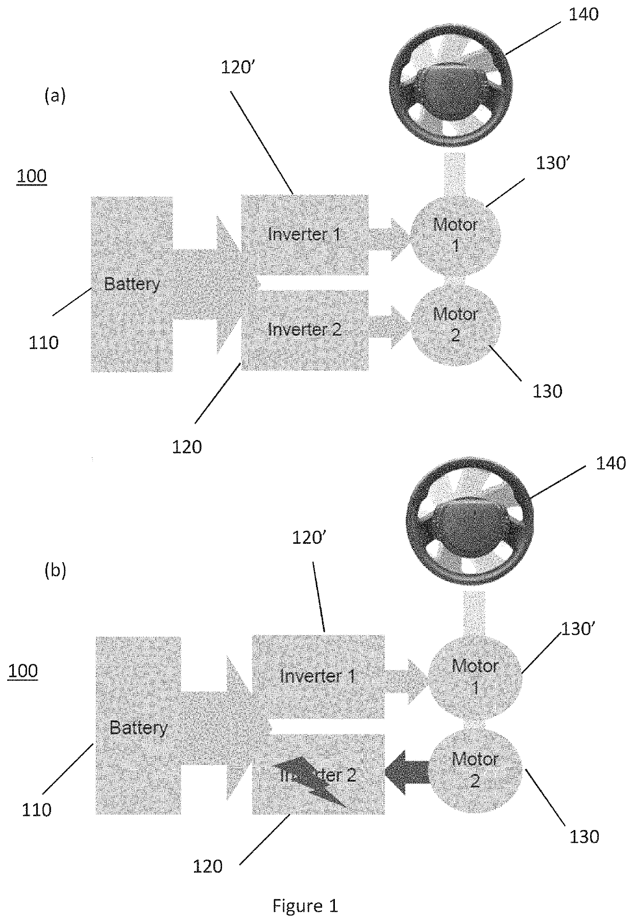
[0079]FIGS. 1(a) and (b) represent a known dual-bridge EPS control system 100. The system comprises first 120 and second 120′ inverter bridges connected to and configured to drive first 130 and second 130′ motors, respectively. When the steering wheel 140 of a vehicle (not shown) is operated by a driver, a demand torque is detected by the system. The motors 130, 130′ generate an assistance torque, dependent on the demand torque and vehicle speed, which acts on the steering rack to assist steering the vehicle. The two motors 130, 130′ may be physically located in one housing or separately but, in either case, they act on the same steering rack and, in normal operation, each contribute approximately 50% of the steering power. The motors 130, 130′ may conveniently be brushless 3-phase AC permanent magnet synchronous (PMSM) motors.

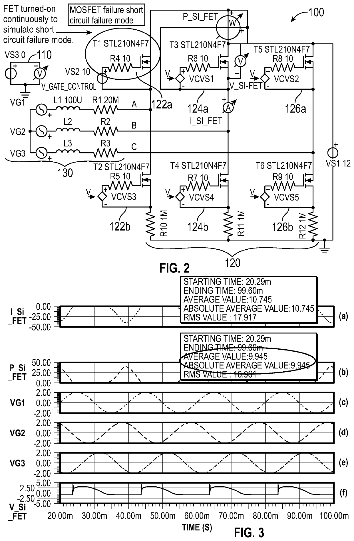
[0080]FIG. 2 shows a known circuit arrangement of an inverter bridge 120 used to drive a 3-phase motor 130, representing one half of the dual-bridge EPS contr...


PUM


Abstract

A method of controlling an electric power assisted steering (EPS) system comprising one or more inverter bridges each connected to a multi-phase motor configured to provide power assist to steering of a vehicle, wherein each inverter comprises a plurality of switching elements each associated with a phase of the motor, the method comprising in response to detecting a predefined event affecting current flow in one or more of the inverter bridges, preventing current flow in said one or more affected inverters by applying a gate-source voltage to one or more of the switching elements of the affected inverter bridge(s), wherein the switching elements are configured to conduct in the off-state when reverse biased beyond a reverse conduction threshold voltage, and wherein applying the gate-source voltage comprises applying a negative gate-source voltage to control the reverse conduction threshold voltage of the switching elements in the off-state only at a time when there is no current flowing in the direction drain to source through the switching device that exceeds a threshold value.

Description

CROSS-REFERENCE TO RELATED APPLICATIONS[0001]This application is a national stage of Great Britain Patent Application No. 1807244.7, filed 2 May 2018, the disclosures of which are incorporated herein by reference in entirety.BACKGROUND TO THE INVENTION[0002]The present invention relates to control of an electric power assisted steering (EPS) system. In particular, the invention relates to eliminating damping currents in EPS systems without the need for a separate phase isolation relay.[0003]Electric Power Assisted Steering (EPS) systems are well known in the prior art. The power generated by an electric motor is used to generate an assistance torque in the steering column in the same direction as a detected demand torque generated by a driver of the vehicle turning a steering wheel.[0004]A typical inverter bridge employed in an EPS system comprises a plurality of semiconductor switching elements which control the current delivered to the motor and thus the rotation of the motor. If ...

Claims


Application Information

Patent Timeline
Patent Type & Authority Patents(United States)
IPC IPC(8): B62D5/04H02P23/14H02P27/08
CPCB62D5/0475B62D5/0481H02P23/14H02P27/08B62D5/0463B62D5/0487B62D5/0484B62D5/046H02P6/10
Inventor RICE, NATHANAELTERDY, TAMAS
Owner TRW LIMITED
Why Eureka
Try Eureka