
Perpetual calendar

a calendar and perpetual technology, applied in the field of perpetual calendars, can solve the problems of merely torn off and thrown away pages, bulky and expensive mechanisms, and obsolete calendars, and achieve the effect of accurately representing sequential dates

Inactive Publication Date: 2005-04-12
DOUBLE FISH DEV
View PDF25 Cites 21 Cited by
  • Summary
  • Abstract
  • Description
  • Claims
  • Application Information

AI Technical Summary

Benefits of technology

In this embodiment, the first number matrix is arranged so that by moving the first surface horizontally in relation to the front panel, a plurality of numbers of the first number matrix is visible through a plurality of windows in the upper rows. The first number matrix is also arranged so that the numbers visible through the windows can accurately represent sequential dates of the upper rows of a calendar for a month starting on any weekday. The second number matrix is arranged so that by moving the second surface horizontally in relation to the front panel, at least one of the numbers in the second number matrix is visible through at least one window in the at least one lower row, and can accurately represent sequential dates for the at least one lower row of a calendar for a month beginning on any weekday and an accurate number of days for any month.

Problems solved by technology

Likewise, an entire calendar is typically obsolete after the particular year has ended, and a user must discard the entire calendar and replace it with a calendar displaying the accurate configuration of days for the current year.
This calendar also includes bulky and expensive mechanisms for translating the motion of the button to the change of the month and day configuration, such that if the user presses the wrong button, the user must recalculate the last day of the month and continue pressing that button until the proper month is again displayed.
Because the month page in a conventional calendar is obsolete at the month's end, the page can merely be torn off and thrown away.
Because the month grid is reused in the perpetual calendars discussed above, any markings on the grid would be carried on to every month, causing confusion and inaccuracy.

Method used


Image

  • Perpetual calendar
  • Perpetual calendar
  • Perpetual calendar

Examples


Embodiment Construction

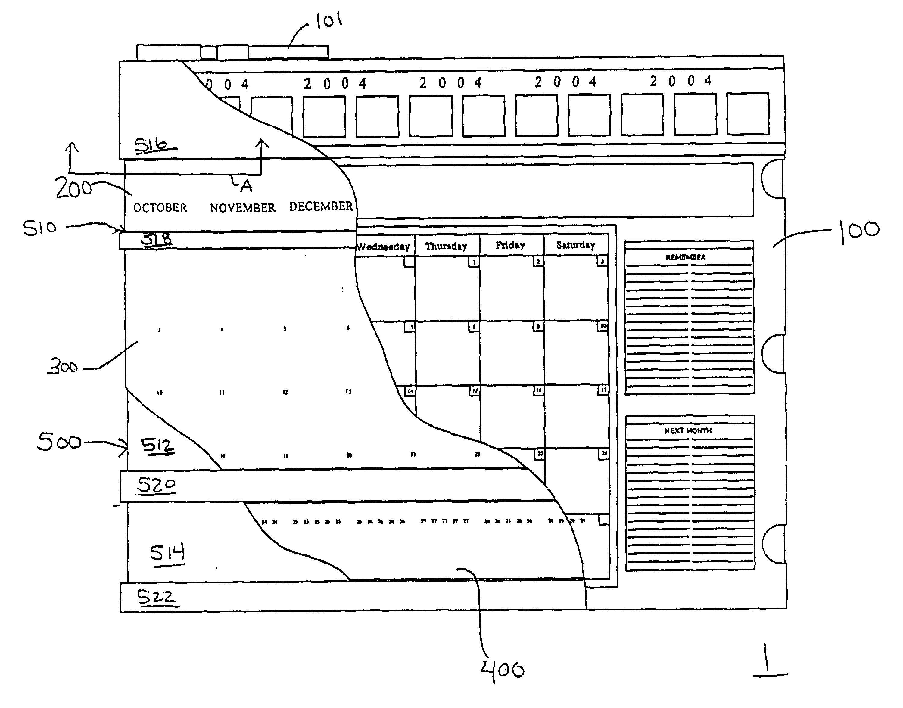
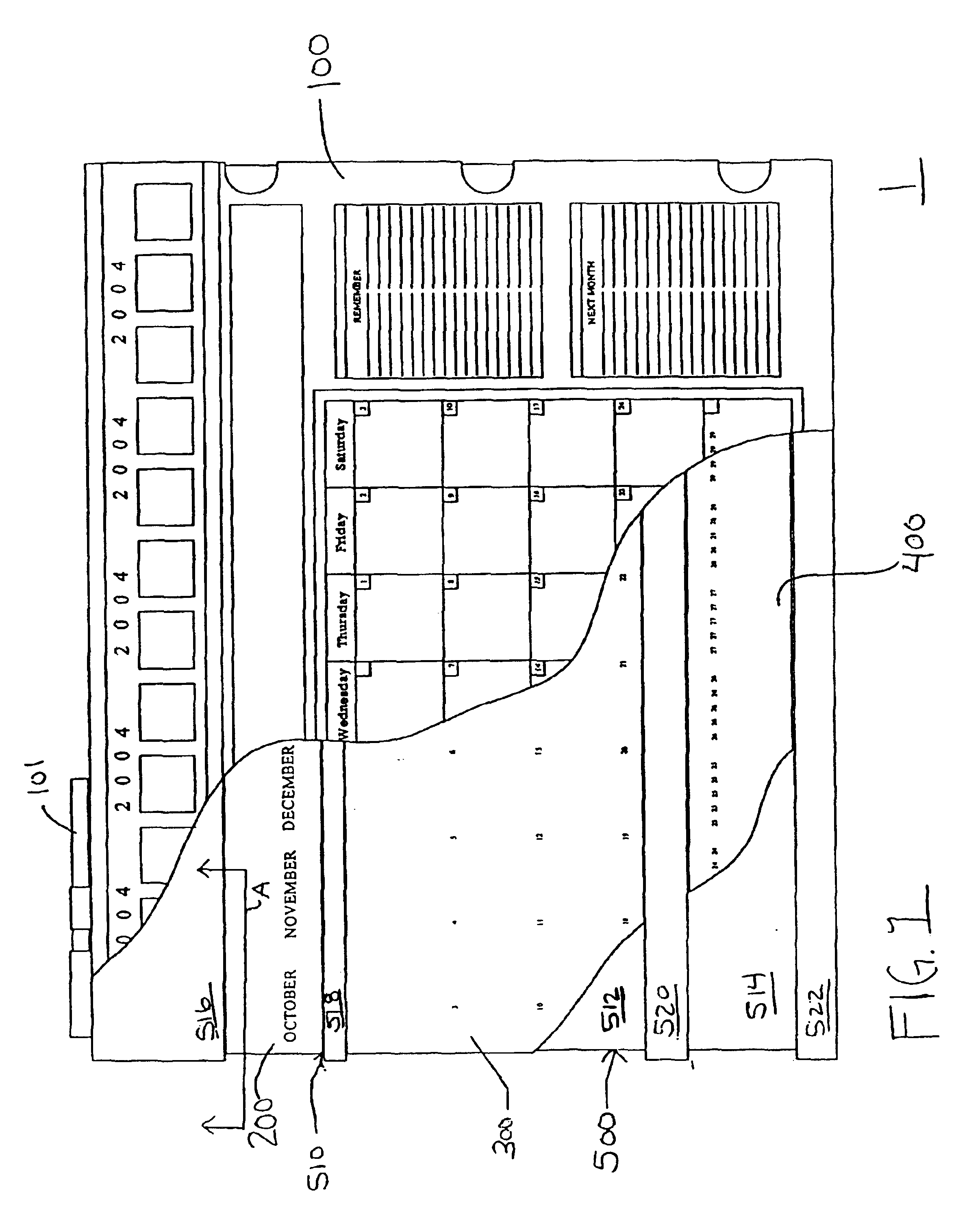
Embodiments of the instant invention are directed to a perpetual calendar and operation thereof. In relation to FIG. 1, one embodiment of a calendar 1 includes a front panel 100 in front of and partially covering a month scroll 200, an upper date scroll 300, and a lower date scroll 400 that horizontally glide along tracks 510, 512, 514 on a base 500. The upper date scroll 300 is located above of the lower date scroll 400 on the base 500.

The month scroll 200, upper date scroll 300 and lower date scroll 400 are formed as loops around the tracks 510, 512 and 514, respectively, of the base 500. The scrolls 200, 300, and 400 are kept in vertical alignment by sitting between raised portions 516, 518, 520 and 522 of the base 500.

In this embodiment, a wet or dry erase marker 101 is removably attached to the top of the calendar 1.

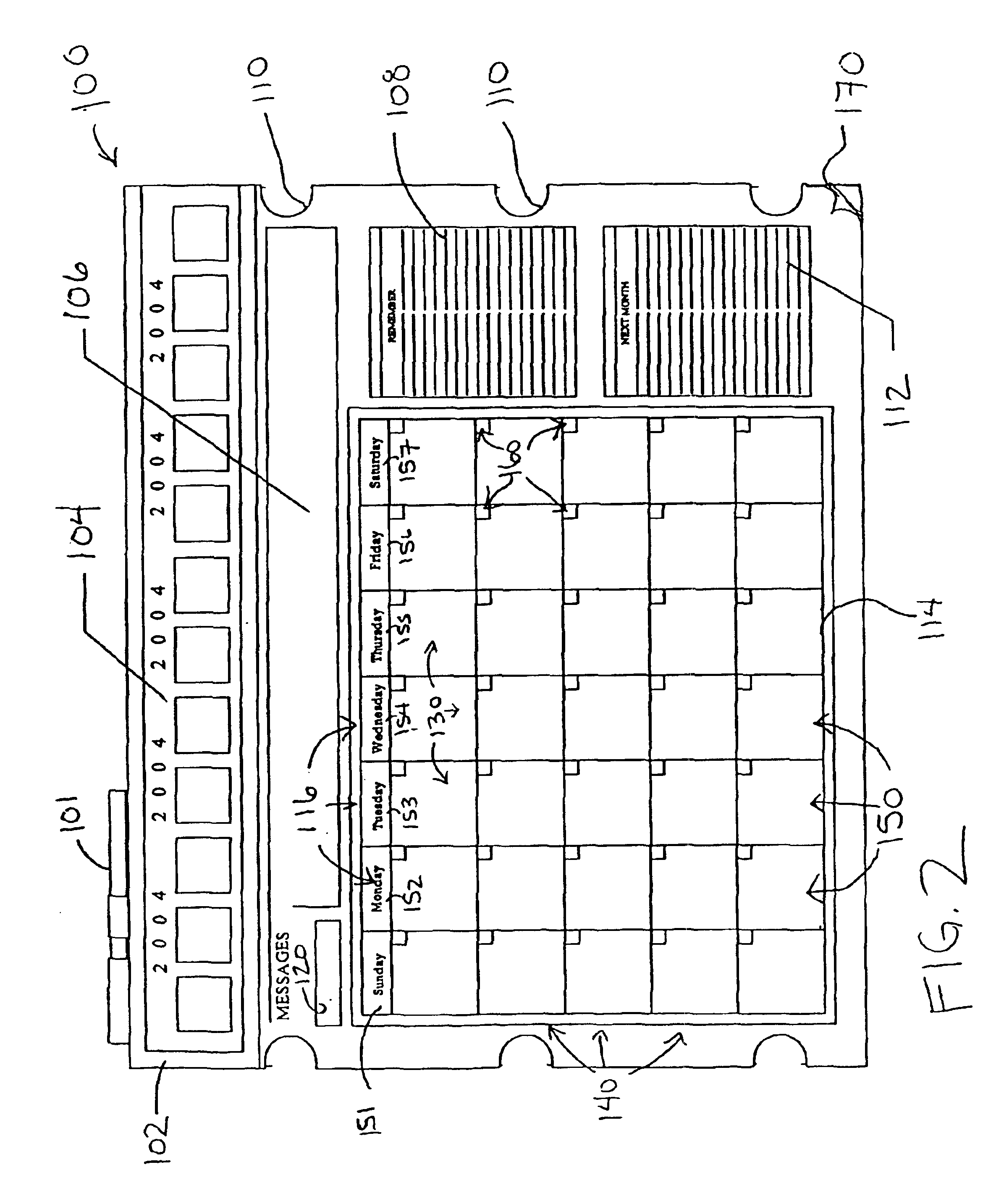
FIG. 2 depicts the front panel 100 in more detail. A month grid 114 of cells 130, arranged in rows 140 and columns 150, is displayed on the front panel 100. Weekday...


PUM


Abstract

A perpetual monthly calendar includes a front panel with a month grid of cells capable of displaying an accurate number and configuration of cells for any month. This embodiment also includes an at least semi-transparent sheet in front of the front panel with a write-on / wipe-off surface.Another embodiment includes a front panel, a first surface with a first number matrix, and a second surface with a second number matrix. The front panel displays a grid of cells with columns representing weekdays and rows representing the upper rows of a calendar and at least one lower row of a calendar. A window is cut out of the front panel in each cell, so that when the first surface or second surface is moved horizontally, the front panel displays an accurate number and configuration of days for any month.

Description

BACKGROUNDMonthly calendars are typically constructed with at least twelve sheets of paper with a single month in one particular year displayed on each sheet. Because the first weekday in each month varies monthly and yearly, each sheet of such a calendar is typically obsolete after the particular month has ended, and a user must display a separate sheet to accurately convey the current month. Likewise, an entire calendar is typically obsolete after the particular year has ended, and a user must discard the entire calendar and replace it with a calendar displaying the accurate configuration of days for the current year.To counter this problem, several “perpetual calendars” have been invented that allow a single calendar to be reused to display multiple months of multiple years with the appropriate starting weekday.One such calendar is described in U.S. Pat. No. 1,042,337 to Gorin. In this patent, a web or ribbon is horizontally movable behind an opaque glass front. The web or ribbon...

Claims


Application Information

Patent Timeline
Patent Type & Authority Patents(United States)
IPC IPC(8): G09D3/00G09D3/10
CPCG09D3/10
Inventor BIANCO, RONALD
Owner DOUBLE FISH DEV
Learn More