Control device for an air valve of an engine

a control device and air valve technology, applied in the direction of valve details, valve arrangements, valve drives, etc., can solve the problems of engine consumption, increased energy consumption, and inability of springs to close the intake valve timely, so as to reduce oil consumption, reduce energy consumption, and reduce oil consumption

Inactive Publication Date: 2005-04-12
LAU
View PDF14 Cites 7 Cited by
  • Summary
  • Abstract
  • Description
  • Claims
  • Application Information

AI Technical Summary

Benefits of technology

With respect to the above problem, the object of the present invention is to provide a mechanism for controlling the intake valve of an internal combustion engine, which mechanism is capable of consuming less energy, i.e. less oil. Through uniquely designed cam and rocker as well as joining mechanism joining the rocker and the stopper, this mechanism does not incur the spring resistance as opening the intake valve, thus the engine per se does not additionally consume energy, so that the object of reducing oil cost and promoting power output may be achieved.

Problems solved by technology

The above described traditional design requires a very large spring force, otherwise, if the rotation is fast, the spring will be incapable of closing the intake valve timely due to its small spring constant.
However, if the spring constant is great, the rocker will correspondingly encounter a greater resistance as the cam pushes the rocker.
In order to overcome this greater resistance, the engine will consume more energy.

Method used


Image

  • Control device for an air valve of an engine
  • Control device for an air valve of an engine
  • Control device for an air valve of an engine

Examples


Embodiment Construction

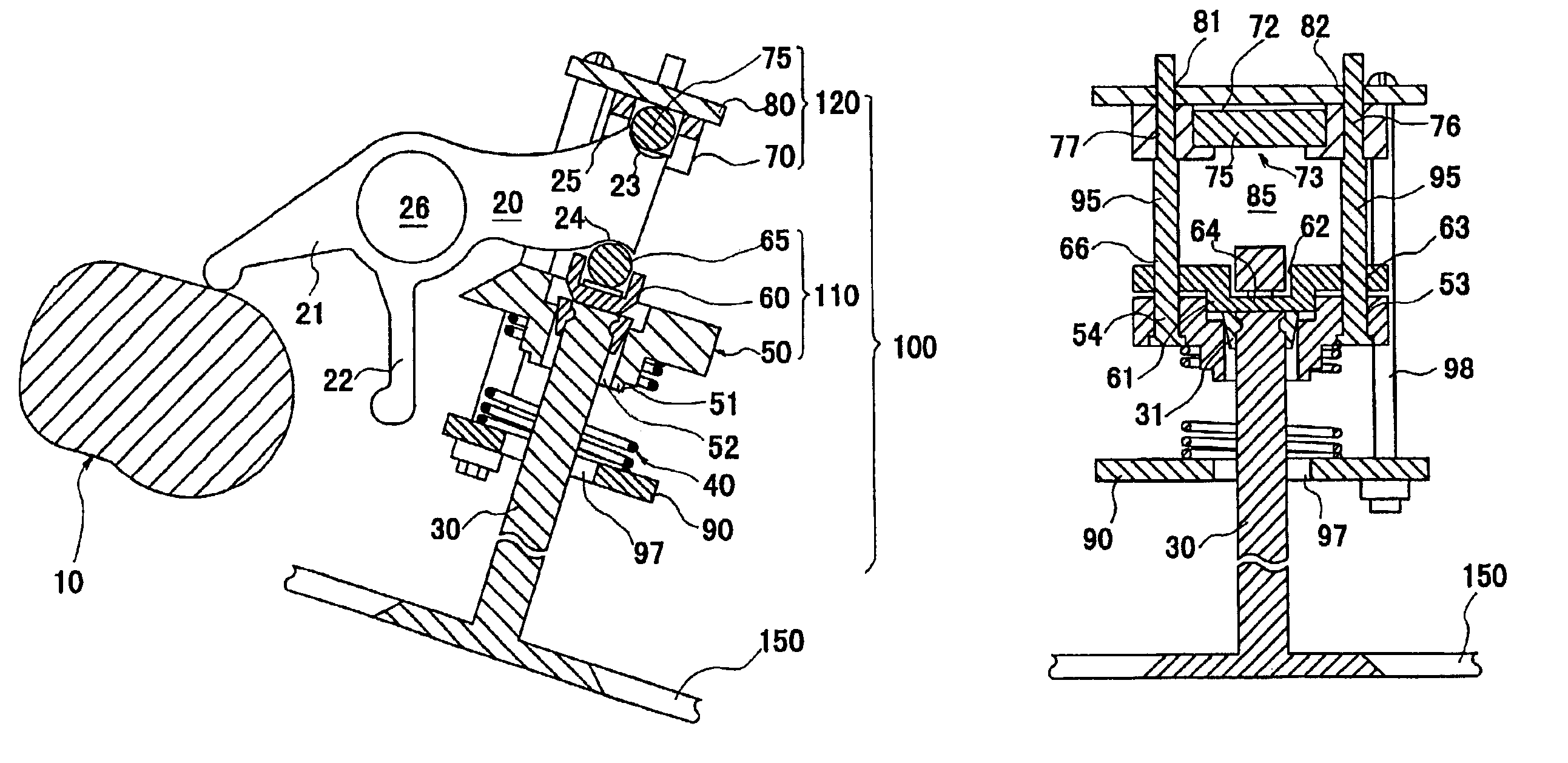
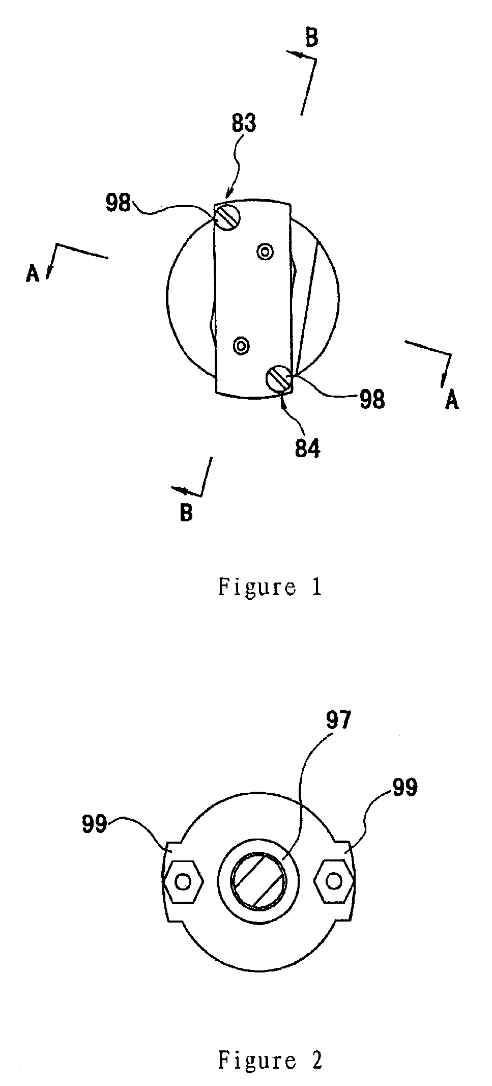
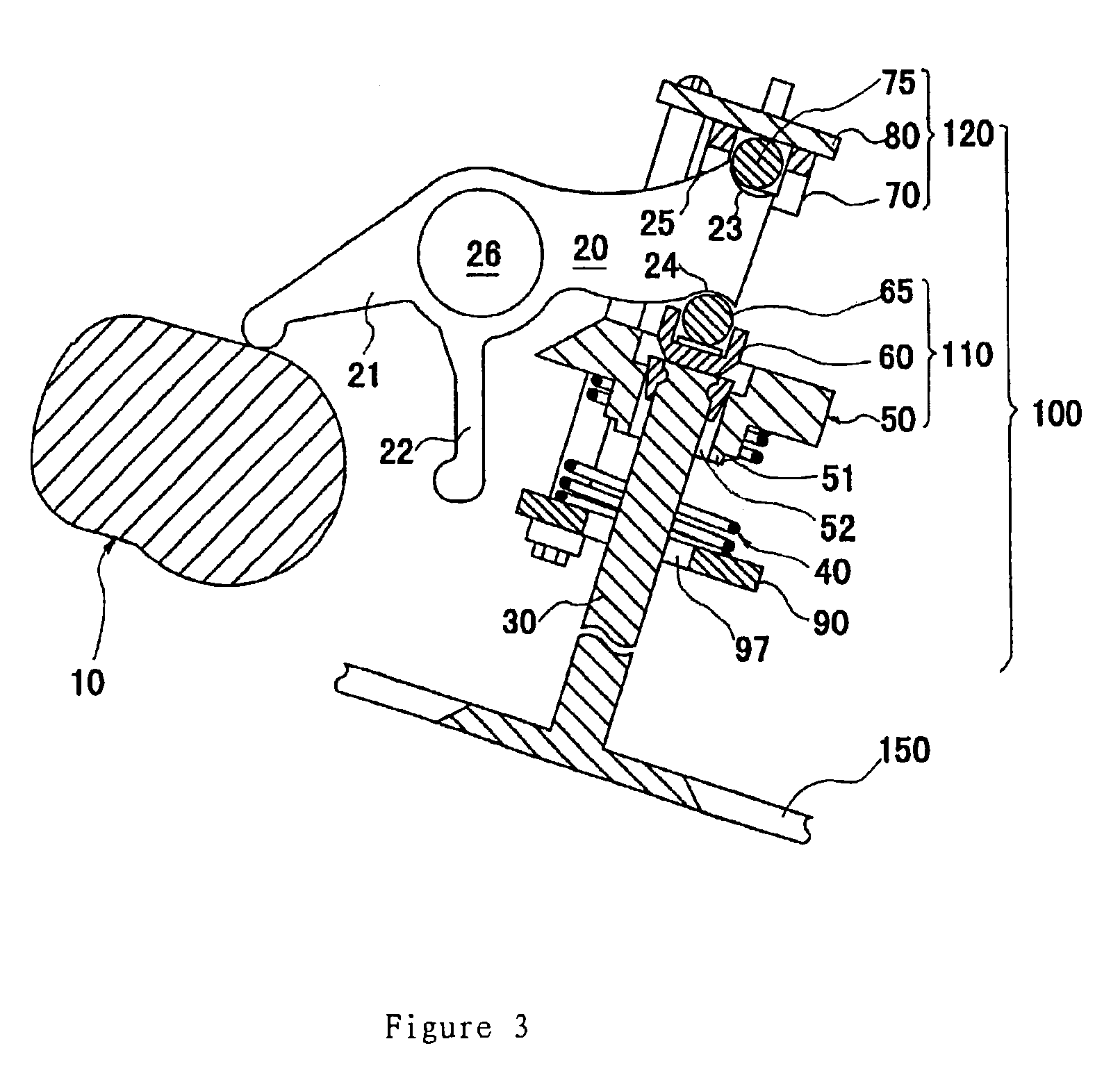
As shown in the figures, the mechanism for controlling the intake valve of an internal combustion engine according to the present invention mainly includes a cam 10, a double-arm rocker 20 and a joining mechanism 100 joining the double-arm rocker and the stopper. Wherein, the cam 10 is formed on the crank shaft and shaped similar to ellipse. The rocker 20 is mounted on a shaft 26. Two arms 21 and 22 are formed in one end of the rocker 20. The ends of two arms are rounded and engage the cam. The other end of the rocker 20 is uniquely shaped to form a first cooperating part 23, a second cooperating part 24 and a third cooperating part 25. The structure of the joining mechanism 100 is in the form of a frame. From the bottom to the top, the joining mechanism 100 comprises a bottom plate 90, a spiral spring 40, a lower cooperating unit 110, first connection elements 95, 95, an upper cooperating unit 120 and a second connection element 98, 98. In one embodiment, the lower cooperating unit...


PUM


Abstract

The present invention provides a mechanism for controlling the intake valve of an internal combustion engine, which mechanism is capable of consuming less energy, i.e. less oil. Through uniquely designed cam and rocker as well as joining mechanism joining the rocker and the stopper, this mechanism does not incur the spring resistance as opening the intake valve, thus the engine per se does not additionally consume energy, so that the object of reducing oil cost and promoting power output may be achieved.

Description

TECHNICAL FIELDThe present invention relates to the intake valve of an internal combustion engine, especially to a mechanism for controlling the intake valve of an internal combustion engine.BACKGROUND OF THE INVENTIONA traditional mechanism for controlling the intake valve of an internal combustion engine is shown in FIGS. 10 and 11, it mainly includes a cam 200, a rocker 300, a stopper 400 and a spring 500. One end of the rocker 300 engages the cam 200, the other end presses the stopper 400. One end of the spring 500 presses the support 700 which is fixedly secured with respect to the cylinder wall 600, the other end abuts against the flange 800 mounted on the end of the stopper 400. As the cam 200 begins to rotate in clockwise direction from the position shown in FIG. 10, it pushes the left end of the rocker 300 upwardly, the rocker 300 then pivots and its right end presses the stopper 400 downwardly, thus, the stopper 400 overcomes the resistance of spring 500 and moves downward...

Claims


Application Information

Patent Timeline
Patent Type & Authority Patents(United States)
IPC IPC(8): F01L1/00F01L3/10F01L1/30F01L1/08F01L1/18
CPCF01L1/08F01L3/10F01L1/30F01L1/12
Inventor LAU
Owner LAU
Why Eureka
Try Eureka