Eureka AIR delivers breakthrough ideas for toughest innovation challenges, trusted by R&D personnel around the world.

Tape feeder for chip mounters

Inactive Publication Date: 2005-04-12
PROTEC CO LTD
View PDF4 Cites 9 Cited by
  • Summary
  • Abstract
  • Description
  • Claims
  • Application Information

AI Technical Summary

Benefits of technology

Accordingly, the present invention has been made keeping in mind the above problems occurring in the prior art, and an object of the present invention is to provide a tape feeder for chip mounters which is operated so that a plurality of locators are restrained in a restraint slot and bearings of the locators alternatively move vertically and horizontally while sliding along the restraint slot by a reciprocating motion of a cam slider, thus repeatedly moving a carrier tape backward while locking the carrier tape and moving the carrier tape forward while releasing the carrier tape, therefore allowing the carrier tape to be fed precisely.
The tape feeder of this invention includes a tension spring, thus providing an air cushioning effect when the air cylinder moves forward.

Problems solved by technology

Because the semiconductor chips received in the carrier tape have a very small size, it is difficult to pick up the semiconductor chips one by one.
Further, it is difficult to treat the semiconductor chips received in the carrier tape, because the semiconductor chips are likely to contamination by foreign materials, such as dust, and a probability of loss is high.
In this case, the semiconductor chips are not precisely fed to target positions and thereby the feeding operation must be set again, therefore deteriorating workability and causing the production of bad products due to a malfunction when the semiconductor chips are picked up.
Further, the volume of the feeder is increased due to a complicated construction, so that it is impossible to realize a slim construction, thus having a low workability.

Method used


Image

  • Tape feeder for chip mounters
  • Tape feeder for chip mounters
  • Tape feeder for chip mounters

Examples


Embodiment Construction

Hereinafter, embodiments of the present invention will be described in detail with reference to the attached drawings.

Reference now should be made to the drawings, in which the same reference numerals are used throughout the different drawings to designate the same or similar components.

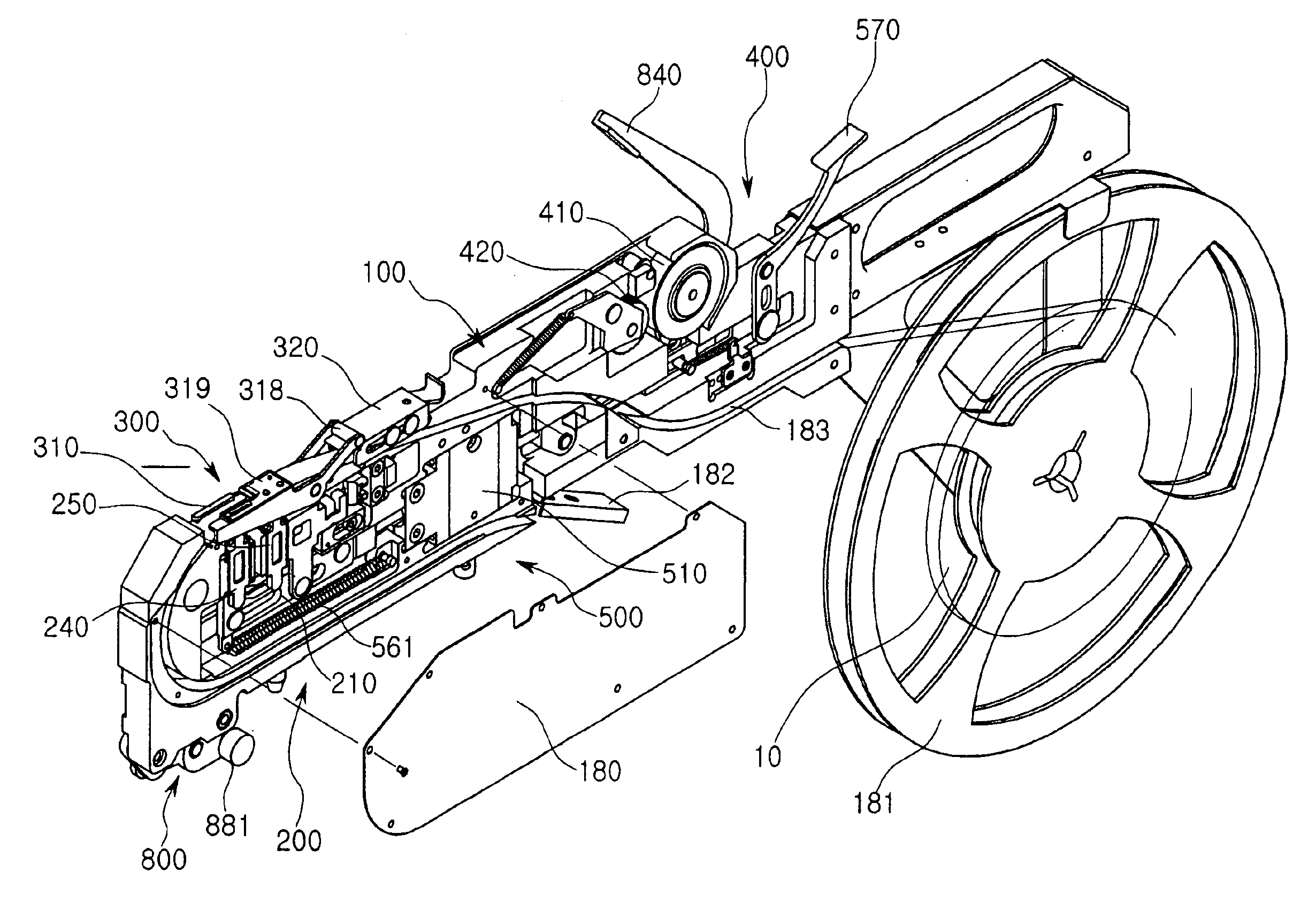
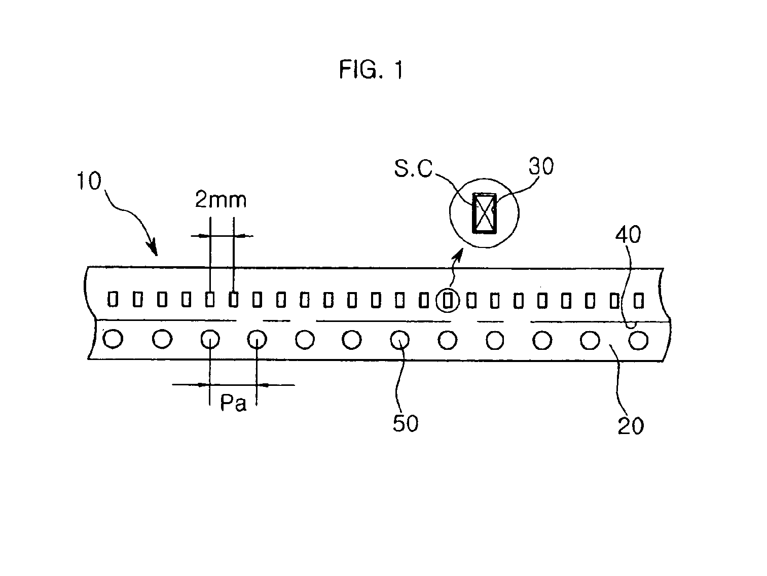
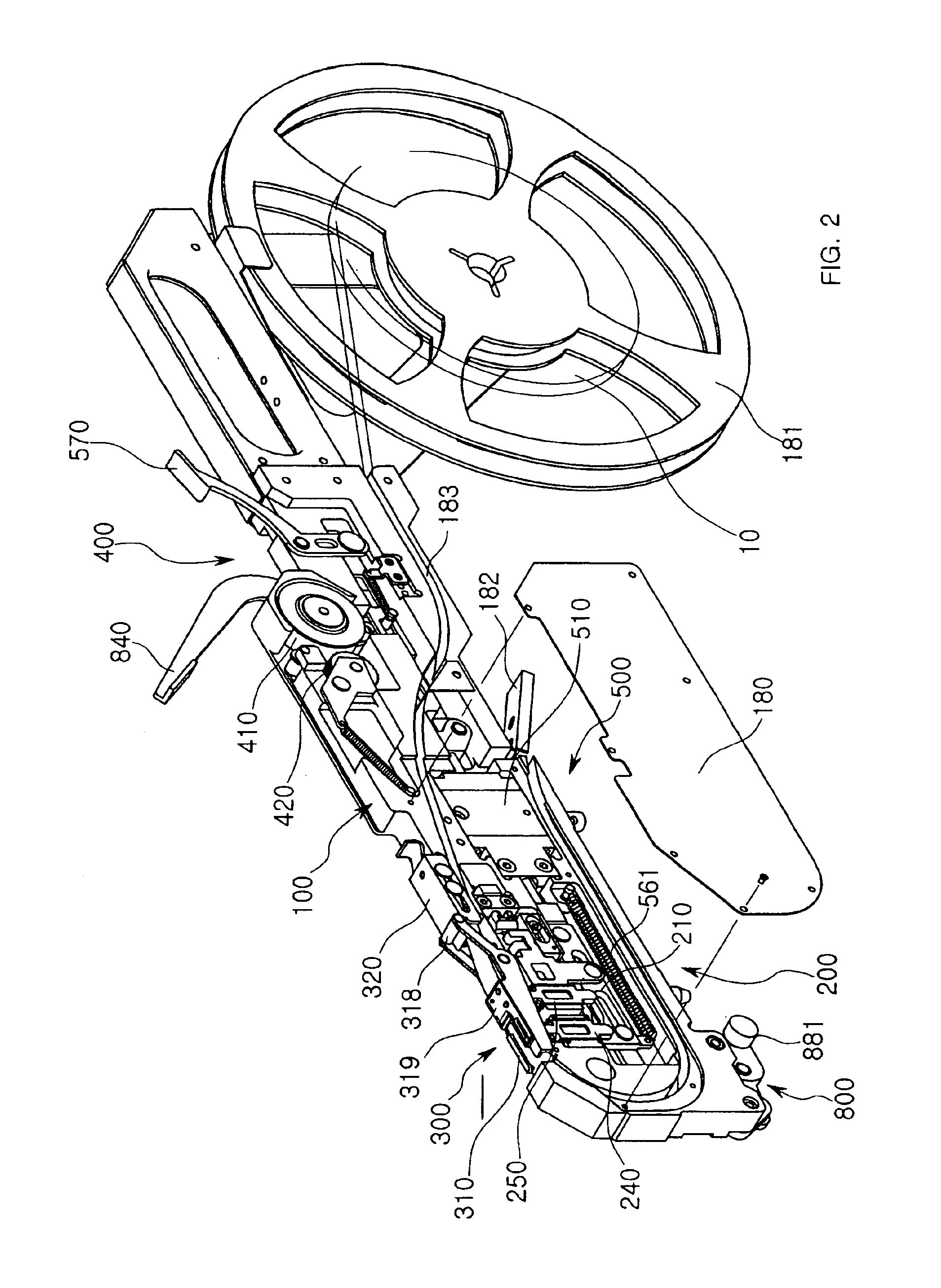
As shown in FIGS. 2 through 15, a tape feeder for chip mounters includes a tape feeding unit 200, a gate unit 300, a vinyl cover discharging unit 400, and a drive unit 500. The tape feeding unit 200 is provided at a front portion of a body 100 which is mounted to a chip mounter, and feeds a carrier tape 10 by a predetermined pitch. The gate unit 300 functions to mount the carrier tape 10 and supports the carrier tape 10 when the carrier tape 10 is fed. The vinyl cover discharging unit 400 includes first and second discharging gears 410 and 420, so that a vinyl cover 40 peeled from the carrier tape 10 is discharged while passing through the first and second discharging gears 410 and 420. The drive uni...


PUM

PropertyMeasurementUnit
Angleaaaaaaaaaa
Widthaaaaaaaaaa
Transparencyaaaaaaaaaa

Abstract

Disclosed herein is a tape feeder for chip mounters. The tape feeder is constructed so that front and rear locators are restrained by a restraint slot of a cam slider moving horizontally, and bearings of the front and rear locators alternatively execute vertical and horizontal movements while sliding along the restraint slot by a reciprocating motion of a cam slider, thus repeatedly moving a carrier tape backward while locking the carrier tape and moving the carrier tape forward while releasing the carrier tape, therefore allowing the carrier tape to be fed precisely. The tape feeder allows the carrier tape to be fed precisely, and prevents chips from being turned over and removed from the carrier tape when a vinyl cover is discharged, thus minimizing a malfunction of the chip mounter during an operation of the chips and thereby maximizing operational reliability. Further, the tape feeder allows the number of elements to be reduced, in addition to achieving a slim construction. Thus, the number of tape feeders mounted to the chip mounter can be increased.

Description

BACKGROUND OF THE INVENTION1. Field of the InventionThe present invention relates generally to tape feeders for chip mounters, and more particularly to a tape feeder for chip mounters which allows a carrier tape loaded with semiconductor chips to be fed by a rectilinear moving unit, thus allowing the carrier tape to be precisely fed, and preventing the chips from being turned over and removed from the carrier tape while a vinyl cover is discharged and thereby minimizing a malfunction when the chips are picked. Therefore operational reliability is maximized, in addition to reducing the number of elements and the volume of the tape feeder.2. Description of the Related ArtGenerally, an electronic part mounter, that is, a chip mounter is a device that picks up electronic parts (semiconductor chips) via a vacuum lifting method by a nozzle of a head which picks and places the electronic parts fed by a feeder, and then mounts the electronic parts on a board.There have been disclosed variou...

Claims


Application Information

Patent Timeline
IPC IPC(8): H05K13/04H05K13/02
CPCH05K13/0417Y10T156/1707Y10T156/1705Y10T156/18Y10T156/1983Y10T156/1994H05K13/0419
Inventor JU, MIN JINKANG, SUNG MINLEE, SOO JINJO, DAE HEE
Owner PROTEC CO LTD
Why Eureka
Eureka Blog
Learn More