
Side mount device for multiple foldable furniture packaging and displaying

a technology for folding furniture and mounting devices, applied in the field of folding furniture, can solve the problems of easy cracking of foldable chairs, easy scratching of foldable tables by their own weight, and headache of users when packing a plurality of foldable furniture, and achieve the effect of effective spa

Inactive Publication Date: 2005-04-12
WOK & PAN IND
View PDF7 Cites 10 Cited by
  • Summary
  • Abstract
  • Description
  • Claims
  • Application Information

AI Technical Summary

Benefits of technology

"The present invention provides a side mount device for multiple foldable furniture that can effectively pack and display the furniture while being space efficient. The device has a reinforced structure that prevents the furniture from being collided with each other and allows for individual holding of the furniture. The device can hold a large quantity of furniture without damaging them, reducing shipping and handling costs for the manufacturer. The device is easy to use and does not require expensive or complicated structures."

Problems solved by technology

However, it is a headache for the user to pack a plurality of foldable furniture.
For example, the foldable tables must be overlappedly stacked up together such that the foldable tables will be easily cracked by their own weights.
Therefore, while transporting the foldable chairs, not only a few foldable chairs are packed together for easily transportation but also the foldable chairs will be easily scratched by the adjacent foldable chairs.
In addition, the major drawback of the foldable furniture is that when they are well packed, the user must take the foldable furniture at the outermost position.
In other words, the foldable furniture at the mid-position of the packaging is impossible to be taken out because the whole stack of the foldable furniture may be collapsed, which may cause a serious injury to the user.

Method used


Image

  • Side mount device for multiple foldable furniture packaging and displaying
  • Side mount device for multiple foldable furniture packaging and displaying
  • Side mount device for multiple foldable furniture packaging and displaying

Examples


Embodiment Construction

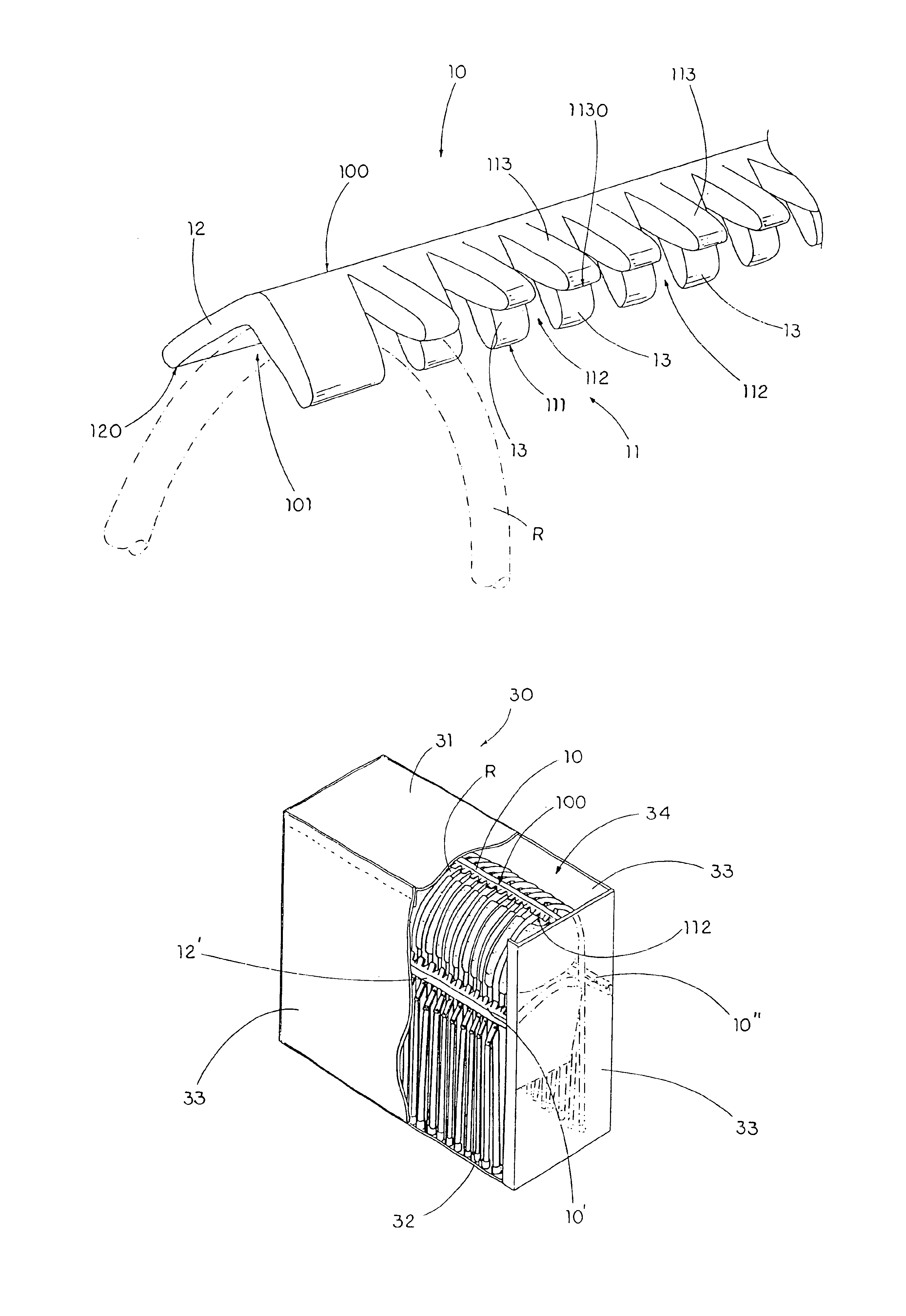
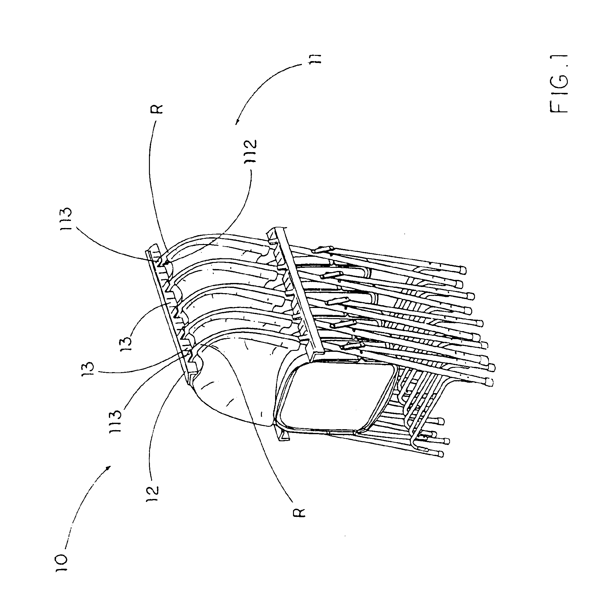
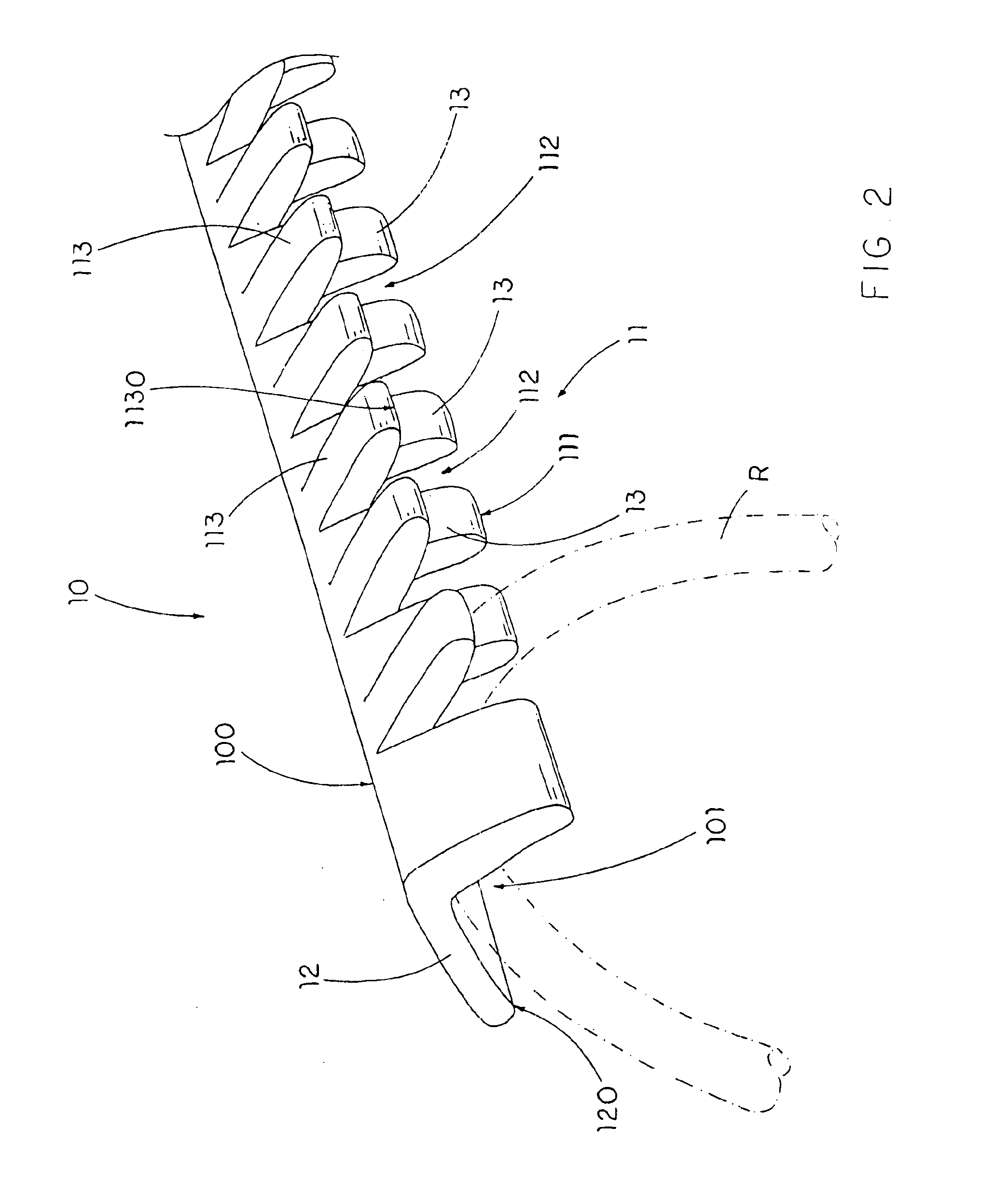
[0025]Referring to FIGS. 1 and 2 of the drawings, a side mount device according to a preferred embodiment of the present invention is illustrated, wherein the side mount device is capable of substantially holding a plurality of foldable furniture for packaging and displaying purpose. Accordingly, each of the foldable furniture has a side rim R extending along two side edges and a top edge thereof.

[0026]As shown in FIG. 2, the side mount device comprises an elongated mold strip 10 comprising a first reinforcing panel 11 and a second reinforcing panel 12 longitudinally extended from the first reinforcing panel 11 along a common line-edge 100 to define a longitudinal mounting channel 101 therebetween.

[0027]The first reinforcing panel 11 has a longitudinal guider edge 111, a plurality of mounting slots 112 spacedly and transversally extended from the longitudinal guider edge 111 towards the common line-edge 100 for slidably receiving predetermined side rim portions R of the foldable fur...


PUM


Abstract

A side mount device, which is adapted for mounting on multiple foldable furniture each having a side rim portion, includes an elongated mold strip including a first reinforcing panel and a second reinforcing panel longitudinally extended therefrom to define a longitudinal mounting channel therebetween. The first reinforcing panel has a longitudinal guider edge, a plurality of mounting slots spacedly and transversally extended from the longitudinal guider edge for slidably receiving the side rim portions of the foldable furniture into the mounting channel so as to spacedly hold the foldable furniture in position, and a plurality of retaining arms which are extended from upper ends of the mounting slots respectively and arranged for pressing on the side rim portions of the foldable furniture when the side rim portions of the foldable furniture are slid through the mounting slots respectively.

Description

BACKGROUND OF THE INVENTION[0002]1. Field of Invention[0003]The present invention relates to a foldable furniture, and more particularly to a side mount device for multiple foldable furniture, which can well pack and display the foldable furniture while being space effective.[0004]2. Description of Related Arts[0005]A conventional foldable furniture, such as a foldable chair or a foldable table has become very popular since the foldable furniture is economy and cheap, and can be quickly and easily folded for carriage and storage and unfolded for use. Especially when some participant-intensive activities take place in multi-function rooms or designated areas, the foldable furniture can be temporary set up in minutes. After the functions, the foldable furniture can be quickly folded up for storage.[0006]Such conventional foldable furniture comprises a supporting panel and a leg frame pivotally connected thereto wherein the foldable furniture is capable being folded between a set-up po...

Claims


Application Information

Patent Timeline
Patent Type & Authority Patents(United States)
IPC IPC(8): B65D57/00B65D85/62B65D85/64
CPCA47C31/11B65D85/62B65D2585/648B65D57/005
Inventor TSAI, FRANK
Owner WOK & PAN IND
Learn More