Worklight

a technology for working lights and stands, applied in the direction of machine supports, outdoor lighting, coupling device connections, etc., can solve the problems of unstably supporting the worklight on the stand, the adjustment of the projecting angle of the worklight, and so as to prevent the tipping of the worklight, enhance the loading ability of the worklight stand, and fold quickly and easily

Inactive Publication Date: 2005-04-12
TSAO FRANK
View PDF2 Cites 44 Cited by
  • Summary
  • Abstract
  • Description
  • Claims
  • Application Information

AI Technical Summary

Benefits of technology

Another object of the present invention is to provide a worklight stand, wherein the ground legs are pivotally connected to the central shaft to radially extend therefrom so that when the ground legs are radially folded to the unfolded position, the worklight stand can well support the worklight in a stable manner so as to prevent the tipping of the worklight.
Another object of the present invention is to provide a worklight stand, which can be quickly and easily folded for carriage and storage and unfolded for substantially supporting the worklight thereon.
Another object of the present invention is to provide a worklight stand, wherein the weight of the worklight applied on the central shaft will further ensure all the ground legs at the unfolded position.
Another object of the present invention is to provide a worklight stand, wherein the ground legs can reinforce the central shaft and enhance the loading ability of the worklight stand by evenly distributing the weight of the worklight to the ground through the ground legs.
Another object of the present invention is to provide a worklight stand, wherein the structural design of the present invention can automatically lock up the worklight stand at its folded position by the strengthen of the ground legs and at its unfolded position by the weight of the worklight. In other words, the worklight stand can be stably remained at its folded and unfolded positions without employing any locking device.
Another object of the present invention is to provide a worklight stand, which successfully provides an economic and efficient solution for detachably supporting the worklight to elevate the floor-type worklight few feet off of the ground in a stable manner.

Problems solved by technology

However, the stand-type worklight has several drawbacks.
However, the rotational movement of the worklight is restricted by the pivot legs 5A so that the adjustment of the projecting angle of the worklight will be limited.
However, if the worklight is relatively heavy, such as 50 lbs or more, the rotational movement of the worklight for adjusting the projecting angle thereof will cause the unstably support of the worklight on the stand.
In other words, it is a hassle for the user to adjust the projecting angle of the worklight once the worklight is supported on the stand.

Method used


Image

  • Worklight
  • Worklight
  • Worklight

Examples


Embodiment Construction

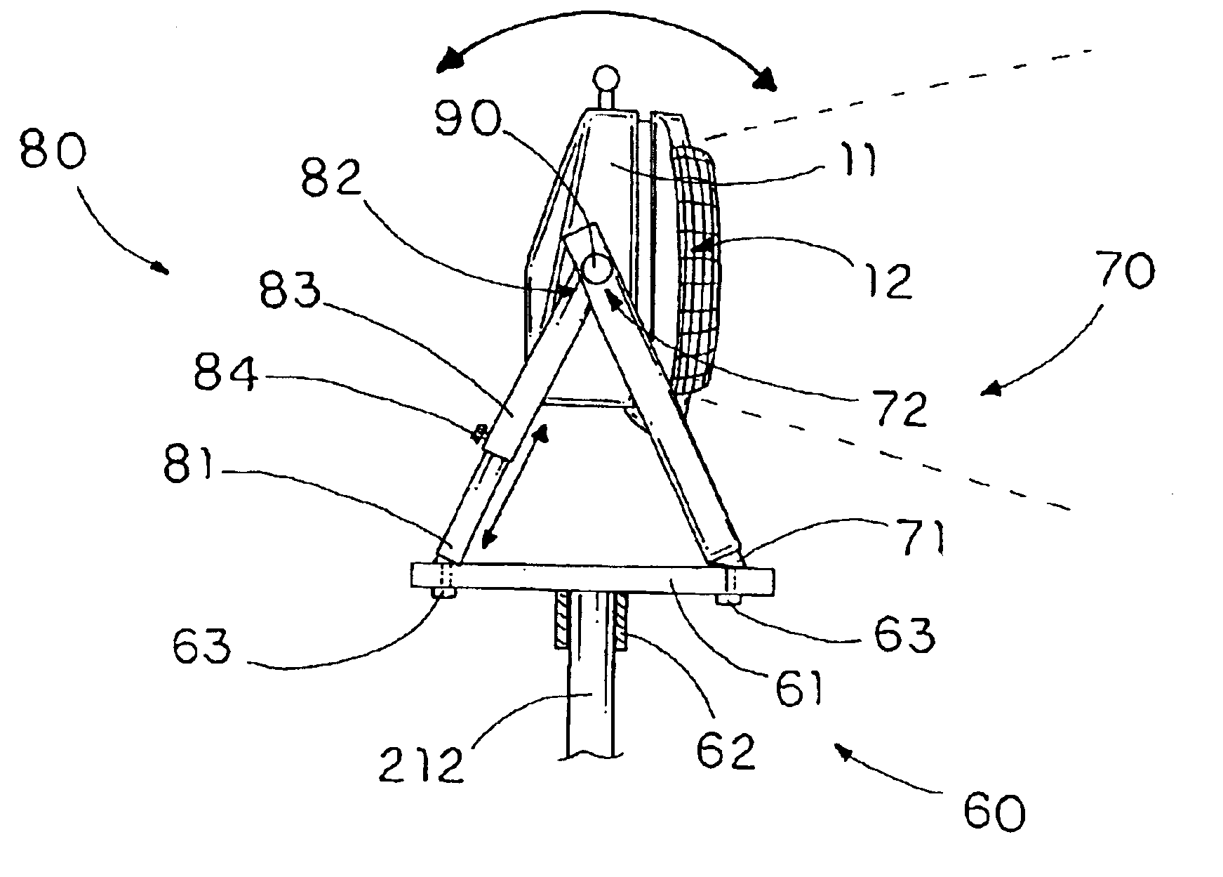
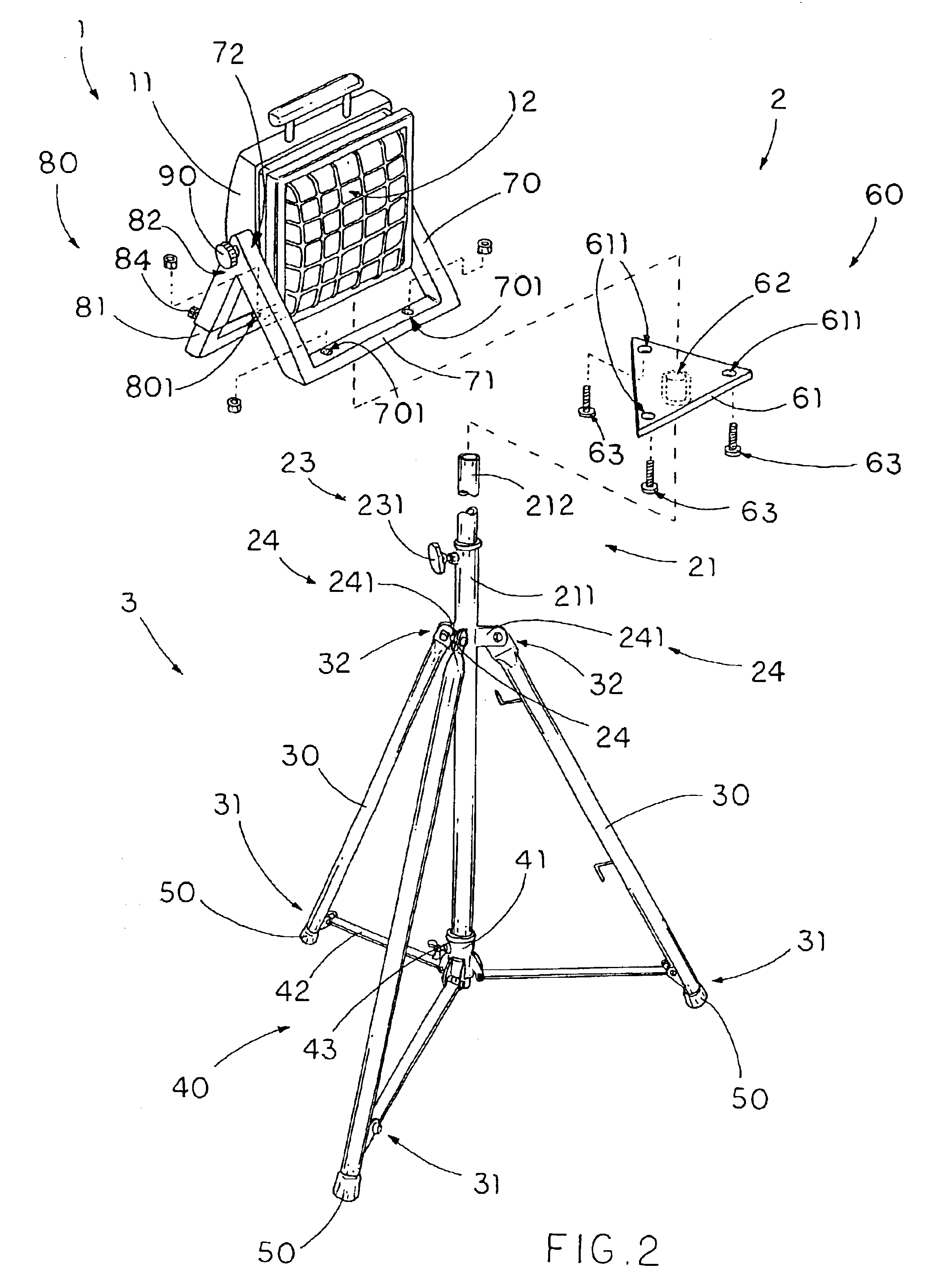
Referring to FIG. 2 of the drawings, a worklight stand according to a preferred embodiment of the present invention is illustrated, wherein the worklight stand is capable of supporting a worklight 1 on a support surface. The worklight comprises a worklight housing 11 for receiving a light source 12 therein and a worklight stand 2.

The worklight stand 2 comprises a U-shaped supporting leg 70 having a lower supporting base 71 and two upper hinge ends 72, a U-shaped pivot leg 80 having a lower standing base 81 and two upper pivot ends 82, wherein the two hinge ends 72 of the supporting leg 70 are pivotally connected with the two pivot ends 82 of the pivot leg 80 respectively, and a locker joint 90 pivotally connecting the two hinge ends 72 of the first pivot leg 70 at two sidewalls of the worklight housing 11 so as to lock up the worklight housing 11 in position to obtain a light projecting angle thereof.

The worklight stand further comprises a foldable stand 3 and a supporting frame 60,...


PUM


Abstract

A worklight includes a worklight housing for receiving a light source therein and a worklight stand including a U-shaped supporting leg having a lower supporting base and two upper hinge ends pivotally connected to the worklight housing, and a U-shaped pivot leg having a lower standing base and two upper pivot ends, wherein the two hinge ends of the supporting leg are pivotally connected with the two pivot ends of the pivot leg respectively. The worklight stand further includes a foldable stand and a supporting frame, which is supported on foldable stand, detachably mounted to the supporting base of the supporting leg and the standing base of the pivot leg in space apart manner such that the worklight housing is substantially supported on the supporting frame and is elevated via the foldable stand in a stable manner.

Description

BACKGROUND OF THE PRESENT INVENTION1. Field of InventionThe present invention relates to a supporting frame for a portable light, and more particularly to a worklight stand, which can be quickly and easily unfolded for substantially supporting a worklight thereon and for selectively adjusting a projecting angle of the worklight.2. Description of Related ArtsPortable worklights are considered as one of the common tools for illumination. Generally, there are two types of worklight, which are floor-type worklight and stand-type worklight, sold commercially. The floor-type worklight is usually placed on a floor through the base of the worklight which typically elevate light housing of the worklight a few inches off of the floor. The stand-type worklight incorporates with a stand to elevate the light housing of the worklight several feet off of the floor.The stand-type worklight, such as U.S. Pat. No. 6,213,626, would be beneficial and more economical in comparison with the floor-type wo...

Claims


Application Information

Patent Timeline
Patent Type & Authority Patents(United States)
IPC IPC(8): F21V21/06
CPCF21V21/06F16M11/245F16M11/2014F16M11/10F21W2131/1005
Inventor TSAO, FRANK
Owner TSAO FRANK
Why Eureka
Try Eureka