

Method and apparatus for filtering an optical beam
a filtering method and optical beam technology, applied in the field of wavelength-agile optical filters, can solve the problems of small tuning range of 3 nm for dfb laser transmitters, and the inability to assign arbitrary channels for dfb laser transmitters, and achieve the effect of precise tuning and compact form factor
- Summary
- Abstract
- Description
- Claims
- Application Information
AI Technical Summary
Benefits of technology
Problems solved by technology
Method used
Image

Examples
example
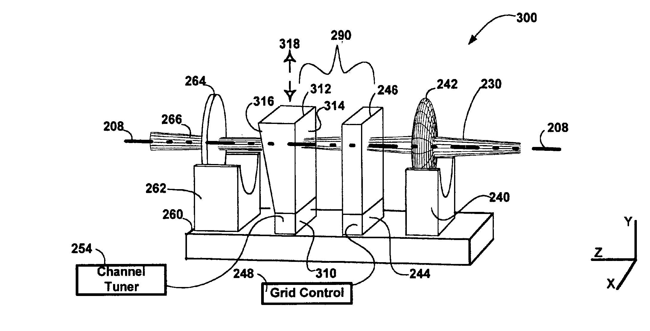
From a default configuration, where the laser frequency is selected at the wavelength of overlap between the two etalons, the laser can be tuned. As the temperature of the second etalon is changed, it's free-spectral range will change. Given enough change in FSR2, the overlap wavelength will “snap” by FSR1, and a new laser frequency will be selected. One can select FSR1=50 GHz, for example, which corresponds to approximately 2 mm of BK7 glass.
The following example shows how to determine the required optical path length change (e.g. a combination of thermal expansion and temperature dependent index change) to achieve a single channel snap. Assuming a channel spacing of 50 GHz and that the grid generator is 1.999 mm of BK7, with a FSRGridGen=50 GHz. If the Finesse is 200, the transmission 1 / e2 half-width is ωo=FSR / F=0.25 GHz, and for simplicity, we can choose FSRChannelSel=50.25 GHz. The thickness of the channel selector etalon is therefore 1.989 mm. The wavelengths of interest where ...
PUM
 Abstract
Description
Claims
Application Information