
Method and apparatus for vehicle integrated chassis control system

a chassis control system and chassis technology, applied in the direction of process and machine control, cycle equipment, instruments, etc., can solve the problems that traditional chassis subsystems cannot adapt or actively respond in real time to a change in driving mod

Inactive Publication Date: 2005-04-12
GM GLOBAL TECH OPERATIONS LLC
View PDF30 Cites 45 Cited by
  • Summary
  • Abstract
  • Description
  • Claims
  • Application Information

AI Technical Summary

Benefits of technology

In one embodiment, an integrated chassis control system for a vehicle having at least one vehicle subsystem is provided, which comprises; at least one sensor for sensing at least one vehicle parameter, at least one vehicle control system for adjusting the at least one vehicle subsystem, a driving mode switch for selecting at least one driving mode, and a controller responsive to the at least one sensor and the driving mode switch. The controller is adapted for controlling the at least one vehicle control system in accordance with the at least one driving mode.
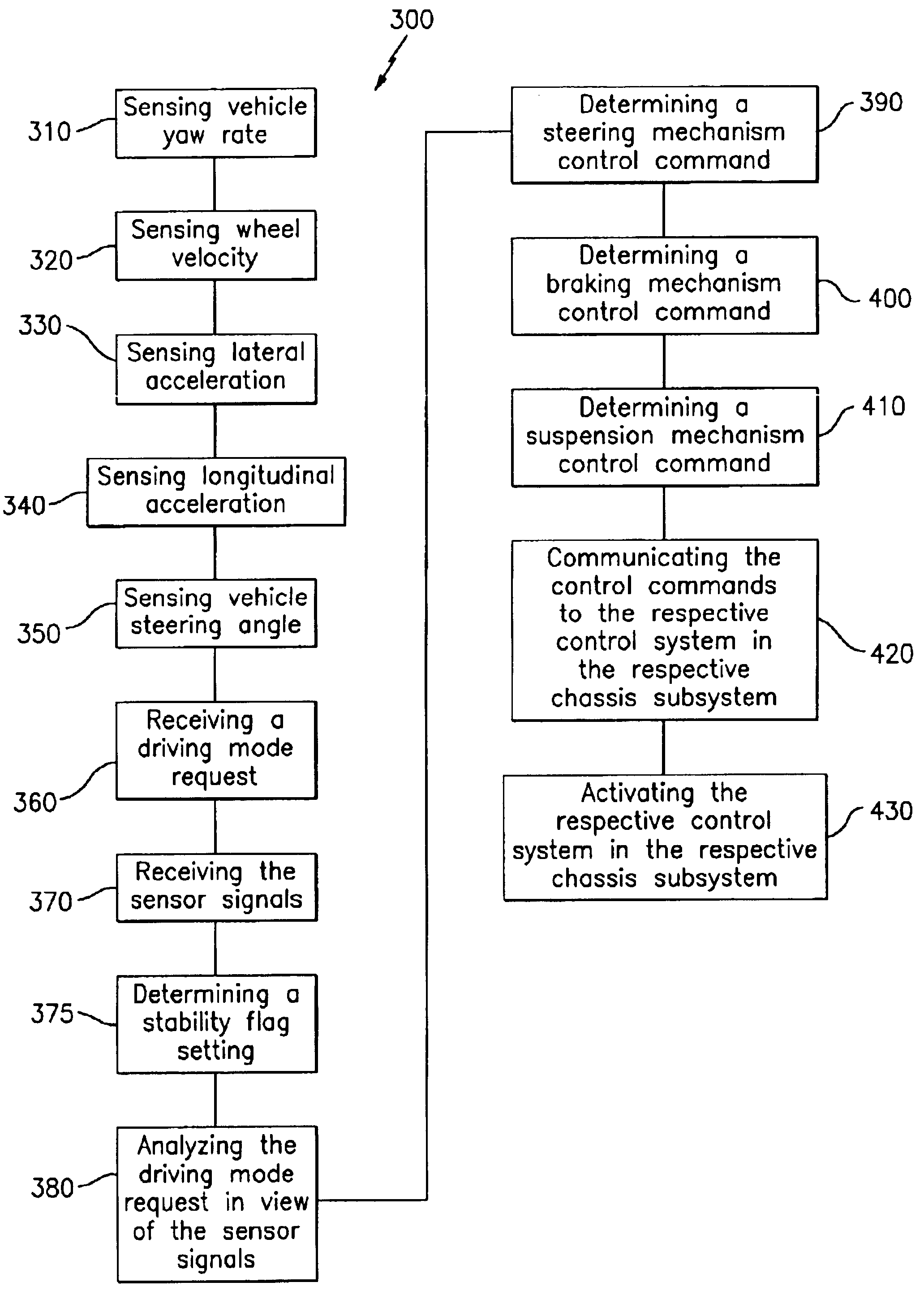
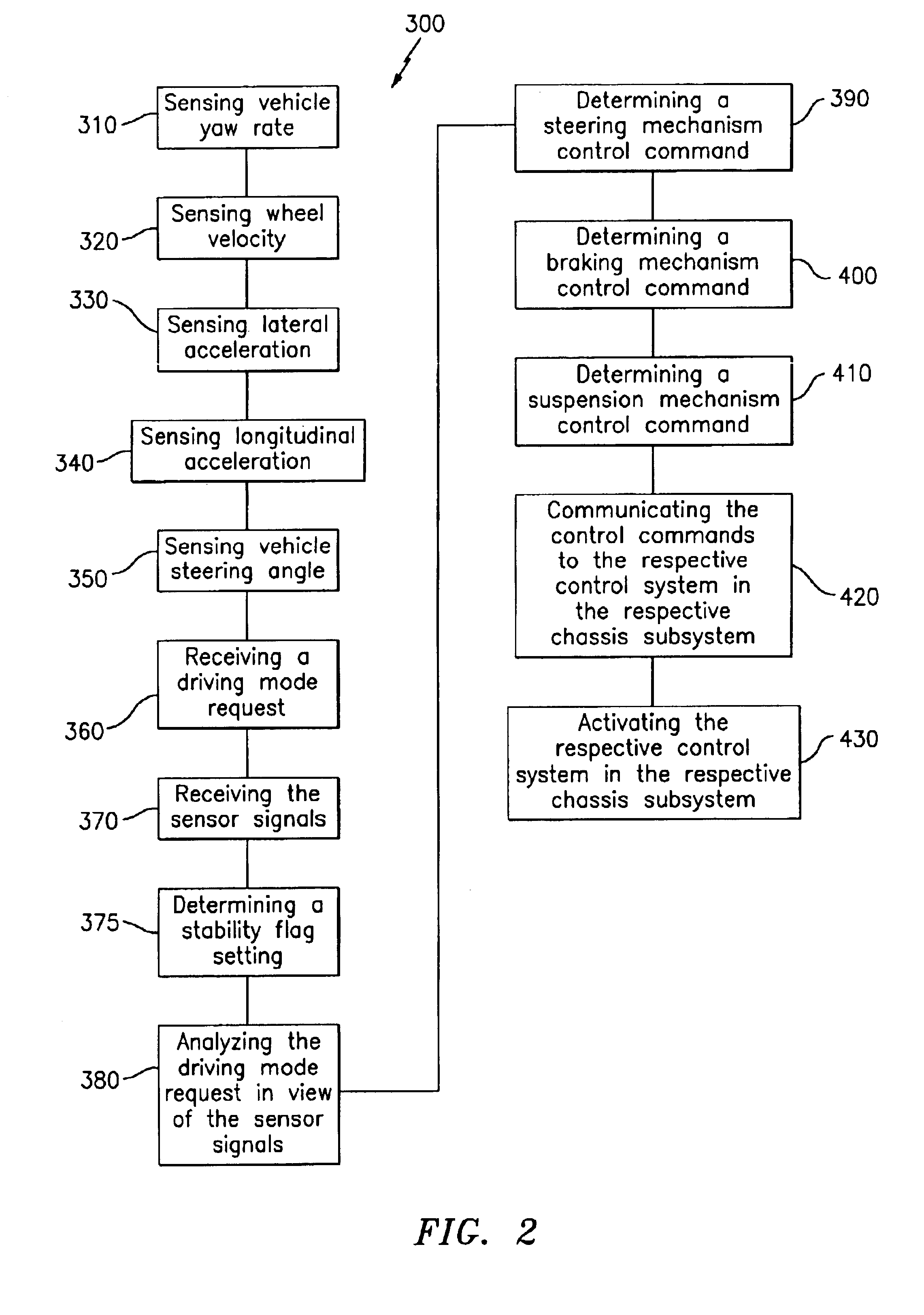
In another embodiment, a method for actively controlling an integrated chassis system for a vehicle is provided, which comprises; sensing at least one vehicle parameter, receiving at least one vehicle parameter signal representative of the at least one vehicle parameter, receiving a driving mode signal representative of a driving mode request, determining a stability flag setting in response to the at least one vehicle parameter signal and at least one programmed parameter, analyzing the driving mode signal in view of the at least one vehicle parameter signal and the stability flag setting, determining at least one control command, communicating the at least one control command to at least one vehicle control system, and actuating the at least one vehicle control system for adjusting the at least one vehicle subsystem in response to the at least one vehicle parameter signal, the driving mode signal, and the stability flag setting.

Problems solved by technology

By design, such traditional chassis subsystems cannot adapt or actively respond in real time to a change in driving mode as requested by the driver.

Method used


Image

  • Method and apparatus for vehicle integrated chassis control system
  • Method and apparatus for vehicle integrated chassis control system
  • Method and apparatus for vehicle integrated chassis control system

Examples


Embodiment Construction

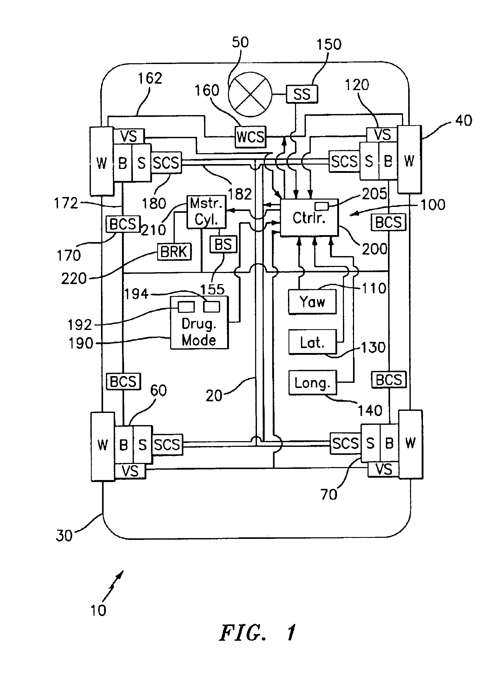
A detailed description of an embodiment of the present invention is presented herein by way of exemplification and not limitation with reference to FIGS. 1-5.

Vehicle

FIG. 1 depicts a generalized schematic of a vehicle 10 having a chassis 20, a body 30 arranged on chassis 20, a set of wheels (“W”) 40 rotationally coupled to chassis 20, a steering mechanism 50 arranged for steering wheels 40, a braking mechanism (“B”) 60 arranged for decelerating wheels 40 upon command, a suspension mechanism (“S”) 70 disposed between wheels 40 and chassis 20 for damping vibration at wheels 40, and an integrated chassis control system (ICCS) 100. The ICCS 100 includes: a yaw rate sensor (“Yaw”) 110 for sensing the actual vehicle yaw rate in degrees-per-second; wheel velocity sensors (“VS”) 120, which is indicative of the vehicle velocity; a lateral acceleration sensor (“Lat”) 130, such as for example an accelerometer, for sensing the absolute value of the vehicle's lateral acceleration in g-force; a lo...


PUM


Abstract

An integrated chassis control system for a vehicle having at least one vehicle subsystem is provided, which includes; at least one sensor for sensing at least one vehicle parameter, at least one vehicle control system for adjusting the at least one vehicle subsystem, a driving mode switch for selecting at least one driving mode, and a controller responsive to the at least one sensor and the driving mode switch. The controller is adapted for controlling the at least one vehicle control system in accordance with the at least one driving mode.

Description

TECHNICAL FIELDThis invention relates generally to an integrated chassis control system for a vehicle and a method of operation thereof, and more particularly to an integral set of chassis subsystems that respond to a central controller.BACKGROUNDTraditional vehicle chassis subsystems, such as steering, braking and suspension subsystems, are passive, meaning that their responsiveness under operating conditions is determined prior to the vehicle leaving the point of manufacture. In such traditional arrangements, the design of the particular chassis subsystem must be determined up-front and must take into consideration the purpose of the vehicle, such as, for example, whether the vehicle will be used primarily as a cruising vehicle or whether it will be used primarily as a sporty, high performance, vehicle. By design, such traditional chassis subsystems cannot adapt or actively respond in real time to a change in driving mode as requested by the driver.SUMMARYIn one embodiment, an int...

Claims


Application Information

Patent Timeline
Patent Type & Authority Patents(United States)
IPC IPC(8): B60G17/015B60T8/58B62D6/00G06F17/00B60G17/0195B60T8/1755B60W10/184B60W10/20B60W10/22B60W40/09B62D101/00B62D111/00B62D113/00
CPCB60G17/0195B62D6/007B60T8/1755B60W40/09B60G2400/104B60G2400/106B60G2400/204B60G2400/41B60G2600/1877B60G2800/912B60G2800/92B60G2800/96B60T2220/02B60T2260/06B60W10/184B60W10/20B60W10/22B60G2400/0523
Inventor GHONEIM, YOUSSEF AHMEDBIELACZEK, CHRISTIAN
Owner GM GLOBAL TECH OPERATIONS LLC
Learn More