Method of installing Y-branch splittable connector

Inactive Publication Date: 2005-04-19
NKF KABEL BV
View PDF16 Cites 104 Cited by
  • Summary
  • Abstract
  • Description
  • Claims
  • Application Information

AI Technical Summary

Benefits of technology

[0014]The invention provides a solution that makes it possible to install branches in an existing duct in which channelization guide tubes and/or cables have already been laid wherein the existing duct can be cut at any point where a branch is desired, with

Problems solved by technology

However, for optical fiber (where a minimum of splices is preferred) the conventional technology does not suffice.
Also excessive digging should be avoided and trench space is limited.
Damage can occur in a variety of ways, namely 1) radial crushing the cable with installation equipment; 2) severe bending, twisting, flexing or stretching damage due to excessive forces applied during installation; 3) damaging the protective cable jacket, such as by abrasion, cracking or cutting the outer protective layer; and 4) long term exposure of the cable to environmental factors which cause thermal cycling.
Splices are time consuming to make and incur considerable installation costs.
Moreover, it is not desirable to have a large number of splice joi

Method used


Image

  • Method of installing Y-branch splittable connector
  • Method of installing Y-branch splittable connector
  • Method of installing Y-branch splittable connector

Examples


Example

[0034]Preferred embodiments of the invention will now be described with reference to various examples of how the invention can best be made and used. Like reference numerals are used throughout the description and several views of the drawing to indicate like or corresponding parts.

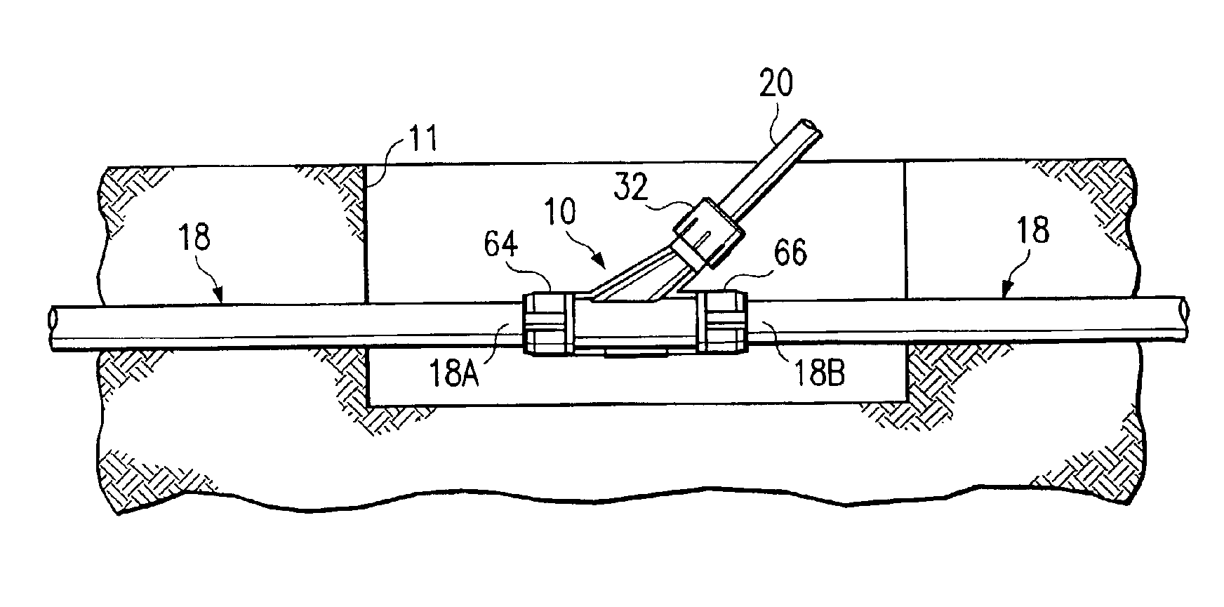
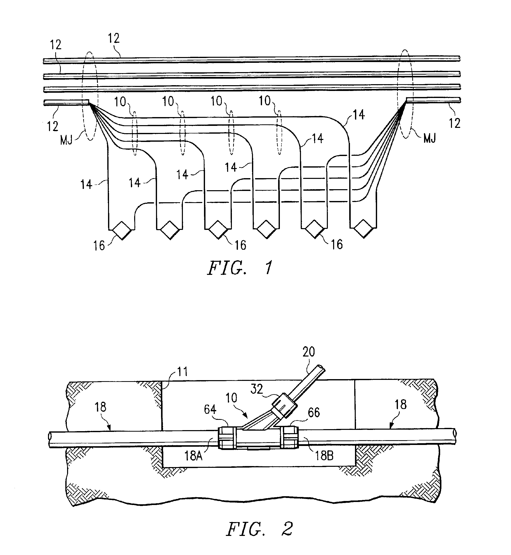
[0035]The splittable Y-branch connector 10 of the present invention is shown installed in a simple access network in FIG. 1 and FIG. 2. Here four feeding 12-fiber cables 12 are spliced at multi-joint splice points MJ to six 2-fiber branching drop cables 14 that make the drop to customer interface access stations 16, everything redundantly connected. The drop cables 14 are guided from the splice points MJ through the customer Y-branch connectors 10 to the customer stations 16, thus allowing one-shot blowing installation of cable to the customer. The entire feeding bundle and Y-branch drop connector 10 fit into a single 40 mm protective duct 18 as shown in FIG. 2. With this configuration it is possible to c...


PUM


Abstract

A method for installing branches in a protective ducting system in which guide tubes and cables have already been laid, wherein at a desired branch location in the protective duct, a splittable Y-branch connector with an inlet opening, an outlet opening and at least one branch opening is installed by cutting a short section from the duct at the desired branch point and exposing the guide tubes and cables, opening the splittable branch connector and arranging it around the exposed guide tubes and cables, and closing and securing the Y-branch connector with splittable coupling collars in such a manner that the inlet opening and the outlet opening engage in sealing manner over the respective cut ends of the existing duct, and the branch opening of the connector is secured by engagement of a branch stub around a branch duct through which a branch guide tube is laid.

Description

CROSS REFERENCE TO RELATED APPLICATIONS[0001]This application is a divisional of U.S. application Ser. No. 09 / 750,802 filed Dec. 27, 2000 now U.S. Pat. No. 6,619,697.STATEMENT REGARDING FEDERALLY SPONSORED RESEARCH OR DEVELOPMENT[0002]Not ApplicableBACKGROUND OF THE INVENTION[0003]This invention relates generally to optical fiber communication systems, and in particular to a split table branch connector and a method for installing the branch connector in an existing protective ducking system in which channelization guide tubes and / or cables already have been installed.[0004]Communication systems employing optical fibers have termination points where optical fiber cross connections, interconnections and terminations are established. The termination points are generally located at a customer's premises, remote from a central office. To reach each termination point, the optical fiber cables must be separated (to form a branch) from a bundle of cables (a “trunk” or “ring”) and then are ...

Claims


Application Information

Patent Timeline
IPC IPC(8): F16L41/02G02B6/44H02G3/02H02G3/06
CPCF16L41/023H02G3/06G02B6/4476G02B6/4464Y10T29/49716G02B6/52
Inventor GRIFFIOEN, WILLEMVAN WINGERDEN, ARIEVAN 'T HUL, CORNELISLOCK, PIETERGREVEN, WILLEMBAKKER, FRANS ROBBERTHAWKINS, DAVID F.
Owner NKF KABEL BV
Why Eureka
Try Eureka