
Adjustable trigger stop

a trigger stop and adjustable technology, applied in the direction of firing/trigger mechanisms, weapons, weapon components, etc., can solve the problems of dangerous situation, potentially dangerous situation, and unlocking the firing mechanism

Inactive Publication Date: 2005-04-19
KEE ACTION SPORTS I +1
View PDF21 Cites 46 Cited by
  • Summary
  • Abstract
  • Description
  • Claims
  • Application Information

AI Technical Summary

Benefits of technology

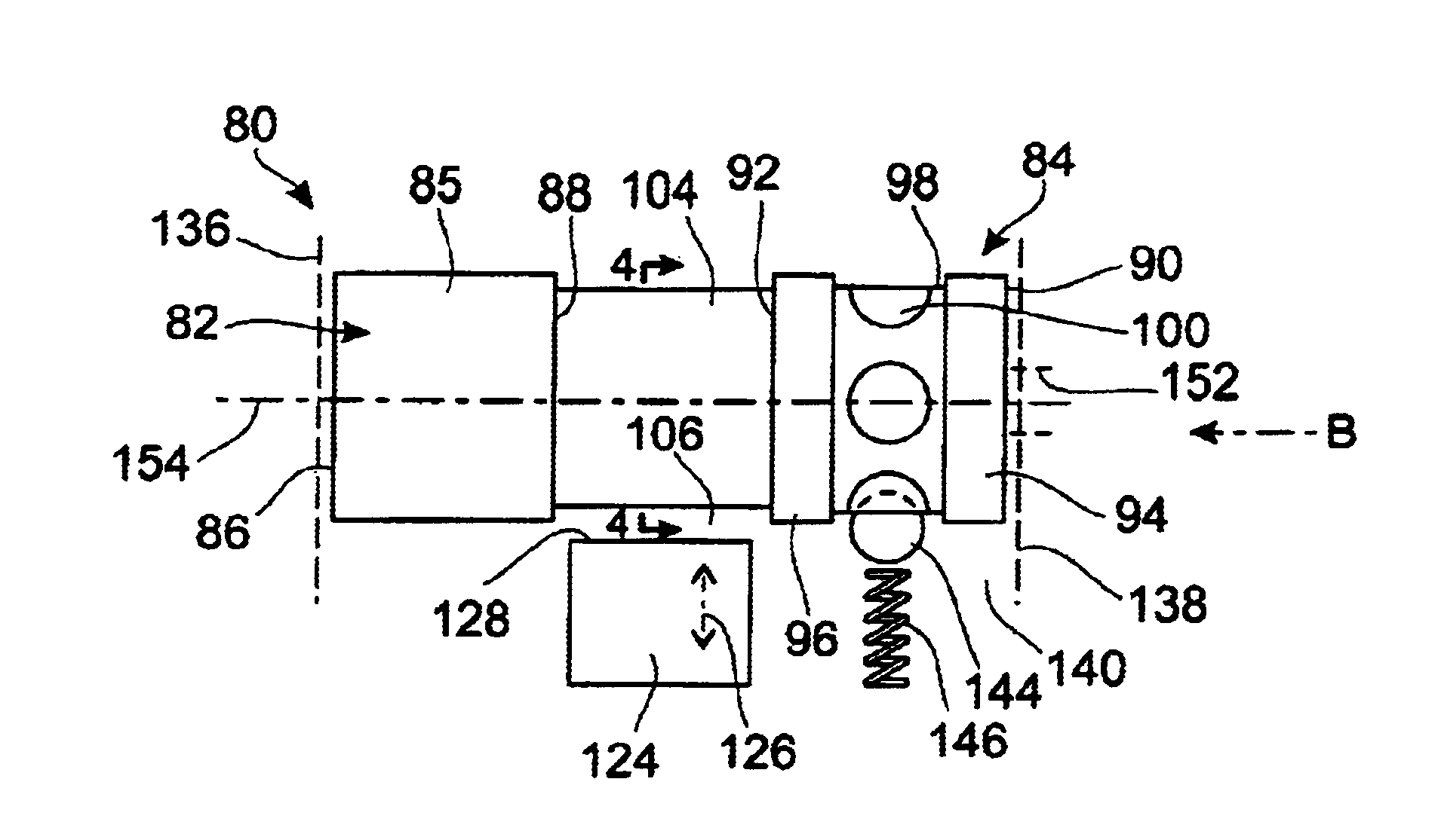
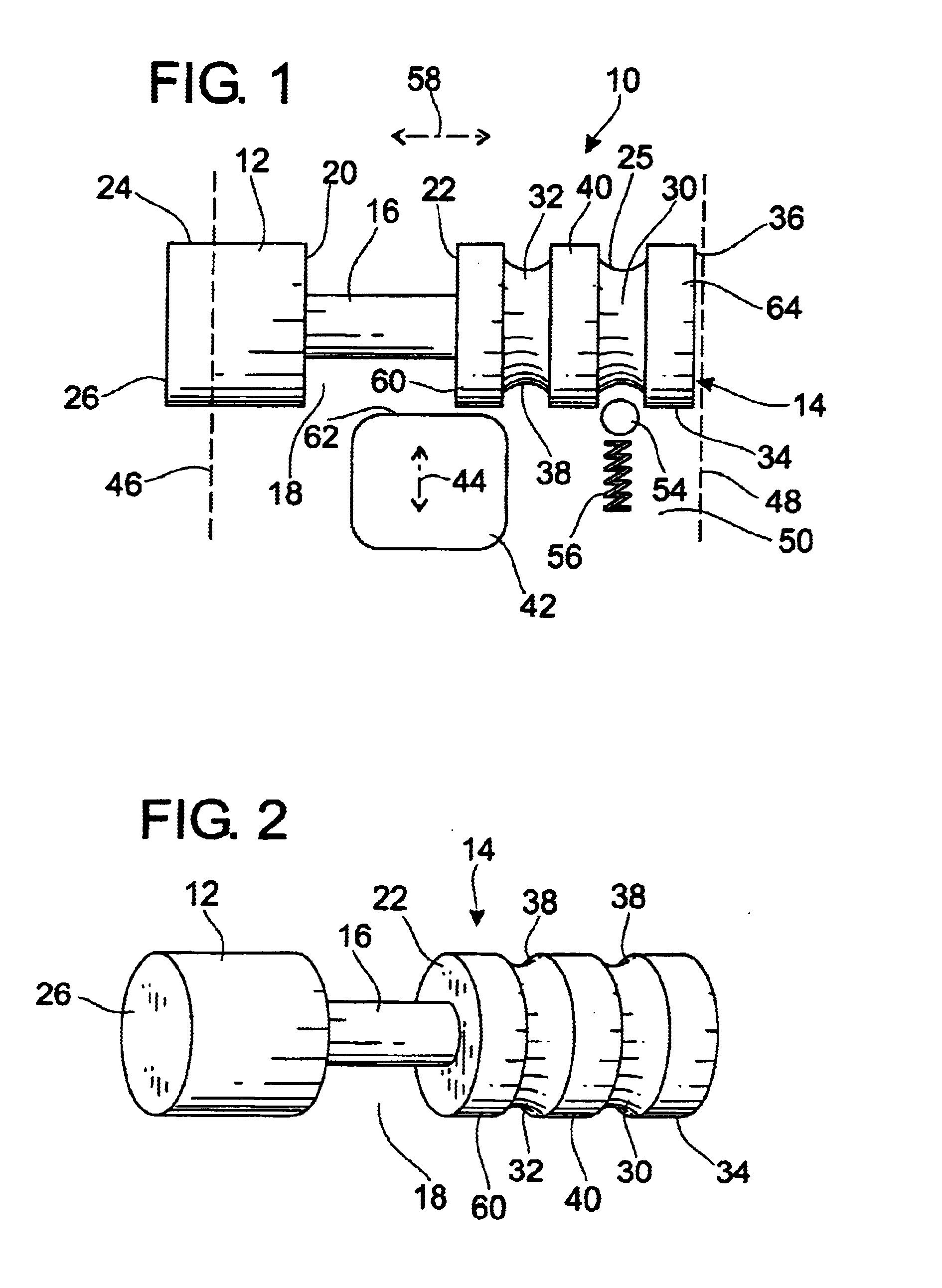
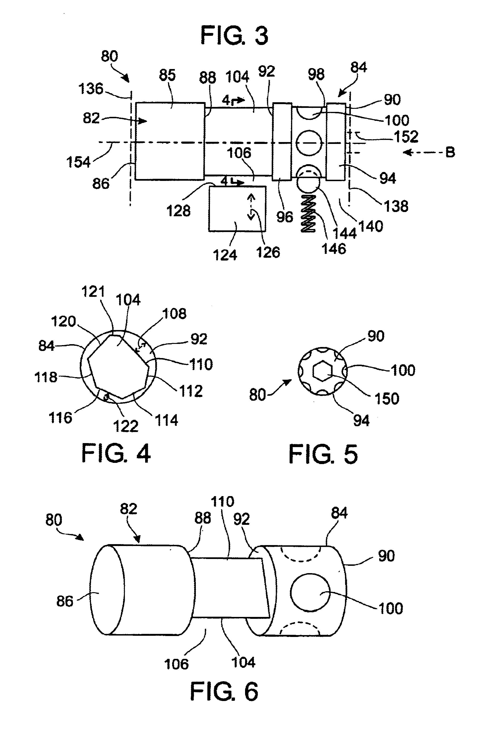
[0009]According to one aspect of the invention, there is provided an adjustable trigger stop assembly comprising a first generally cylindrical lateral arm having an inner end and an outer end and a second generally cylindrical lateral arm having an inner end and an outer end, the first and second lateral arms each having an aligned axis, with the inner ends of the first and second lateral arms respectively facing each other; and an intermediate portion formed on the axis between the inner ends of the first and second lateral arms respectively, the intermediate portion having at least a first facet spaced from the axis and a second facet spaced from the axis, the first and second facets for engaging a trigger so that each permits different amounts of movement of the trigger.
[0011]The invention in one aspect is for a trigger stop mechanism with enhanced safety and / or operational features. The trigger stop mechanism of the invention allows for the more effective locking and unlocking of the trigger stop which would improve the safety characteristics of the weapon, and particularly a paintball marker. Further, the trigger stop mechanism, by its design features and configuration, also allows the user of the paintball marker to make adjustments to the position and effect of the trigger stop mechanism which varies the firing process by determining the rapidity of paintballs fired from the marker in a given period.

Problems solved by technology

One potential problem associated with conventional trigger stops or catches is that the barrel-shaped object which comprises the trigger stop projects outwardly from the trigger frame, or other portion of the paintball marker or gun, presenting itself as a small button, which can be pushed from one direction or another so as to move the catch into the first or second position for locking or unlocking the mechanism.
Such catches may be inadvertently knocked so as to move them from the locked to the unlocked position, causing a potentially dangerous situation.
Further, these trigger stops may indeed be manipulated to the unlocked position by children or inexperienced users, once more causing unlocking of the firing mechanism and creating a dangerous situation.

Method used


Image

  • Adjustable trigger stop
  • Adjustable trigger stop
  • Adjustable trigger stop

Examples


Embodiment Construction

[0023]The invention relates to a trigger stop assembly for use in a weapon, and particularly a paintball gun. The trigger stop assembly comprises a pair of lateral substantially cylindrical portions, and an intermediate portion therebetween. The intermediate portion is multi-faceted so that any one facet creates a recess with respect to the two lateral portions which recess differs in its configuration and characteristics, especially depth with respect to the lateral portions, from other recesses formed by other facets of the intermediate portion. The size of the recess, when the trigger stop is associated with a corresponding sear, determines the extent of movement of the sear, and thus the locked or unlocked condition of the weapon.

[0024]The size of the recess will also have an effect in determining the rate at which paintballs are discharged from the paintball marker, since the depth of the recess directly controls the stroke length of the associated trigger. Depending upon the s...


PUM


Abstract

An adjustable trigger stop assembly comprises a first generally cylindrical lateral arm having an inner end and an outer end and a second generally cylindrical lateral arm having an inner end and an outer end. The first and second lateral arms each have an aligned axis, with the inner ends of the first and second lateral arms respectively facing each other. An intermediate portion is formed on the axis between the inner ends of the first and second lateral arms respectively. The intermediate portion has at least a first facet spaced from the axis and a second facet spaced from the axis, the first and second facets in use engaging a trigger so that each facet permits different amounts of movement of the trigger.

Description

CROSS-REFERENCE TO RELATED APPLICATIONS[0001]This application claims the benefit of U.S. Provisional Application No. 60 / 364,209 filed Mar. 13, 2002, which is incorporated herein in its entirety.FIELD AND BACKGROUND OF THE INVENTION[0002]This invention relates to adjustable trigger stops for guns, and has a particular application with respect to trigger stops used in paintball guns, also known as paintball markers.[0003]In this specification, it should be understood that the word “trigger stop” is used to denote a component in a gun, such as a paintball gun or marker, whose position can be adjusted or varied to place a lock or bar against activation of the firing mechanism. The trigger stop, also known by other names such as a catch, is a broad term used in this document to indicate any physical mechanism which has the effect of locking the weapon. The trigger stop of the invention can also be used to adjust or vary the “travel” of the trigger so that the user can set this parameter ...

Claims


Application Information

Patent Timeline
IPC IPC(8): F41A19/03F41A19/00F41A19/16F41A17/46F41A17/00
CPCF41A17/46F41A19/16F41A19/03
Inventor ORR, JEFFREY GEORGE
Owner KEE ACTION SPORTS I
Learn More