Panel element

a technology of panel elements and elements, applied in the field of panel elements, can solve the problems of relatively laborious and nuisance procedures, and achieve the effect of reliably maintaining a snug clearance-free contact and simple glueless laying

Inactive Publication Date: 2005-04-19
FLOORING IND LTD
View PDF69 Cites 392 Cited by
  • Summary
  • Abstract
  • Description
  • Claims
  • Application Information

AI Technical Summary

Benefits of technology

[0011]The invention is based on the objective of providing panel elements for forming a floor covering permitting simple glueless laying of the floor covering whilst achieving and reliably maintaining a snug clearance-free contact in joining adjoining panel elements.

Problems solved by technology

This is why it is known to fabricate non-generic floor coverings such that the tongue and groove geometries provided therein do not already prevent parting of adjoining floor panel elements so that these elements can be first simply jointed, namely married and not fixedly connected until glued and safeguarded against the cited parting forces whilst, on the one hand, being regularly sealed by the aforementioned glueing procedure so that at the joints of two adjoining panel elements neither moisture nor dirt is able to gain access.
Such a procedure is, however, relatively laborious and a nuisance since several panel elements interlocked by their ends need to be handled.

Method used


Image

  • Panel element
  • Panel element
  • Panel element

Examples


Embodiment Construction

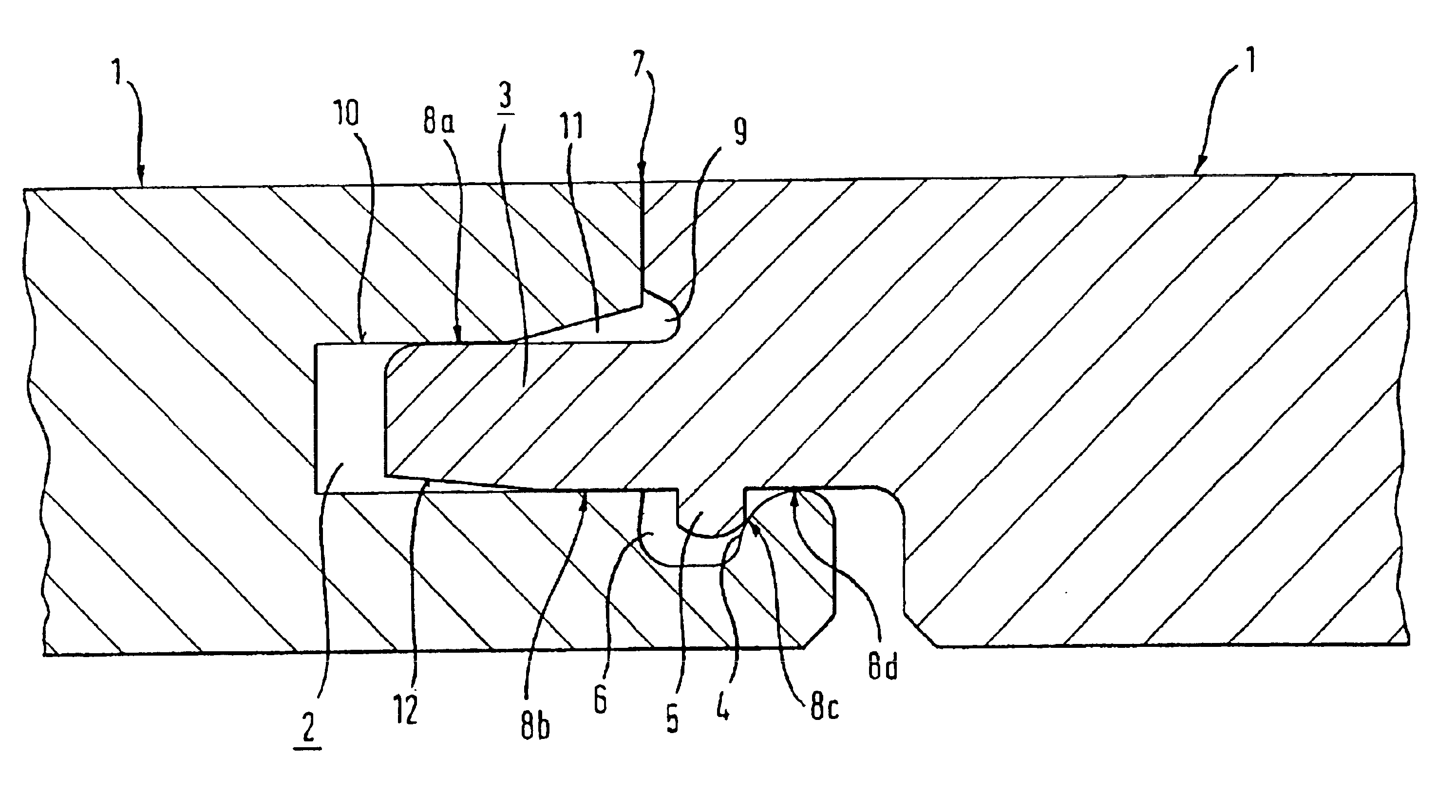
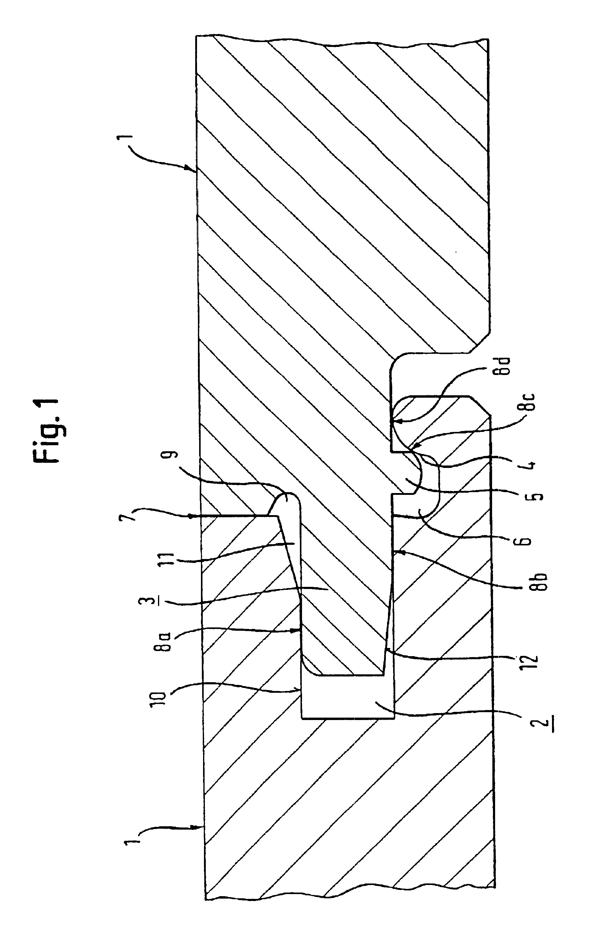
[0042]Referring now to FIG. 1 there is illustrated two panel elements of the same type identified 1, the one panel element 1 comprising a groove 2 and the other panel element 1 a tongue 3 extending into the groove 2 of the adjoining panel element 1. The material thickness of the panel element 1 is slightly more below the groove 2 or above the tongue 3 than below the groove 2 or the tongue 3 respectively so that pressures exerted by human or furniture loads can be accommodated relatively well in loading the tongue and groove joint to a minimum.

[0043]The two panel elements 1 are safeguard against being lifted out of place by the meshing effect of the groove 2, on the one hand, and of the tongue 3 on the other, they likewise being safeguarded against compression forces acting downwards in addition to the support of the panel element 1 by the sub-floor on which the two panel elements 1 are laid.

[0044]The panel elements 1 are safeguarded against parting forces acting transversely to the ...


PUM


Abstract

The invention relates to a panel element for forming a floor covering, consisting of several identical interconnectable panel elements and having the following features: two first sides of each panel element, called the “longitudinal sides”, these sides having a groove and a tongue; the tongue of a panel element which is positioned at an angle with an installation level of a first, identical panel element can be introduced into the groove of the first panel element; the tongue interacts with the groove of the adjacent, identical panel element in such a way that two interconnected panel elements are protected against separating forces which are exerted along both of the axes extending perpendicularly to the longitudinal side of the panel elements; two second sides of the panel element, called the end sides, are provided with fixing means and a groove and tongue, these forming an end-side connection between two adjacent panel elements; the end-side grooves and tongue can be interconnected by means of the panel element being lowered onto an identical panel element that has already been installed, essentially crosswise to the installation level, so that the panel element is protected from lifting forces, i.e. forces which are exerted considerably perpendicularly to the installation level.

Description

[0001]This application is a continuation of prior application number PCT / EP01 / 00359, filed on Jan. 12, 2001, entitled PANEL ELEMENT, and now pending.FIELD OF THE INVENTION[0002]The invention relates to panel elements as set forth in the preamble of claim 1.[0003]Panel elements for forming floor coverings are usually rectangular and elongated, although they may also feature other contours in being configured square, for example. Accordingly, in keeping with the usual rectangular configuration terms such as “side”, “end” or the like are employed in the following without the invention being restricted to elongated panel elements. These terms serve in addition merely to distinguish first and second edges of the panel element each arranged parallel to the other in pairs and at an angle relative to the edges designated otherwise so that the geometry of the panel element provided for the “side” may also be provided at the other, for example, “end”.PRIOR ART[0004]Known from GB 2,256,023 A i...

Claims


Application Information

Patent Timeline
Patent Type & Authority Patents(United States)
IPC IPC(8): E04F15/04B27M3/00B27M3/02E04F13/08E04F15/02
CPCE04F15/02E04F15/04E04F2201/0138E04F2201/0523E04F2201/025E04F2201/041E04F2201/0153
Inventor SCHWITTE, RICHARDMENSING, ANSGAR
Owner FLOORING IND LTD
Why Eureka
Try Eureka