Method and apparatus for performing dynamic mechanical analyses

a dynamic mechanical analysis and analysis method technology, applied in the direction of measuring devices, material strength using repeated/pulse forces, instruments, etc., can solve the problem of displacement not representing an effective tensile elongation of the entire specimen, and the damping constant of an elastic specimen cannot be determined, so as to achieve the effect of excessive elongation

Inactive Publication Date: 2005-04-19
METTLER TOLEDO GMBH
View PDF9 Cites 12 Cited by
  • Summary
  • Abstract
  • Description
  • Claims
  • Application Information

AI Technical Summary

Benefits of technology

[0007]It is therefore the objective of the present invention to propose a method and an apparatus that keep a dynamic mechanical analysis free of the kinds of errors that are introduced by incorrectly selected levels of pre-tension.SUMMARY OF THE INVENTION
[0008]In a dynamic-mechanical analysis method according to the invention, a test specimen is held in a holder device and subjected to a static pre-tensioning force and a time-variable excitation force, and the deformation of the specimen is measured by one or more displacement sensors. The method includes the steps that during application of a variable excitation force one or more decision parameters are determined and compared to one or more given reference values, and that the comparison is used to determine whether or not the test specimen is completely coupled to the excitation device, i.e., in a completely slack-free state, so that the physical values derived from the measurements will not be subject to errors caused by insufficient amounts of pre-tension.
[0009]A dynamic-mechanical analysis apparatus according to the invention includes a control device that directs and controls the analysis process, a holder device to hold the test specimen, an excitation device to apply a static pre-tensioning force and a time-variable excitation force to the test specimen, and at least one displacement sensor to measure the deformation of the test specimen. The control device includes means whereby during application of a variable excitation force one or more decision parameters are determined and compared to one or more given reference values. The result of the comparison is presented in a form that makes it evident whether or not the test specimen is completely coupled to the excitation device so that the physical values derived from the measurements will not have errors caused by insufficient amounts of pre-tension.
[0019]A preferred embodiment of the invention includes a step where following a measurement to determine physical properties of a specimen, the pre-tensioning force is lowered and the one or more decision parameters are evaluated until an asymmetry is found that indicates an insufficient level of pre-tension. At this point, the pre-tensioning force is raised slightly until the asymmetry disappears, so that a sound measurement can be performed for the determination of physical values of the test specimen. This procedure is advantageous in particular for measurements where the temperature approaches the glass transition temperature, because it prevents the pre-tensioning force during the entire measurement series from becoming too high for the progressively softening test specimen and causing an excessive elongation of the latter.

Problems solved by technology

If the pre-tension is less than a minimally required pre-tensioning force, the specimen is not coupled correctly to the excitation device.
In this condition, even a small increase of the force can cause a relatively large amount of displacement, but because of the faulty clamping of the test specimen the displacement does not represent an effective tensile elongation of the entire specimen.
Analogously, a damping constant of an elastic specimen can only be determined at a sufficiently large pre-tensioning force.

Method used


Image

  • Method and apparatus for performing dynamic mechanical analyses
  • Method and apparatus for performing dynamic mechanical analyses
  • Method and apparatus for performing dynamic mechanical analyses

Examples


Embodiment Construction

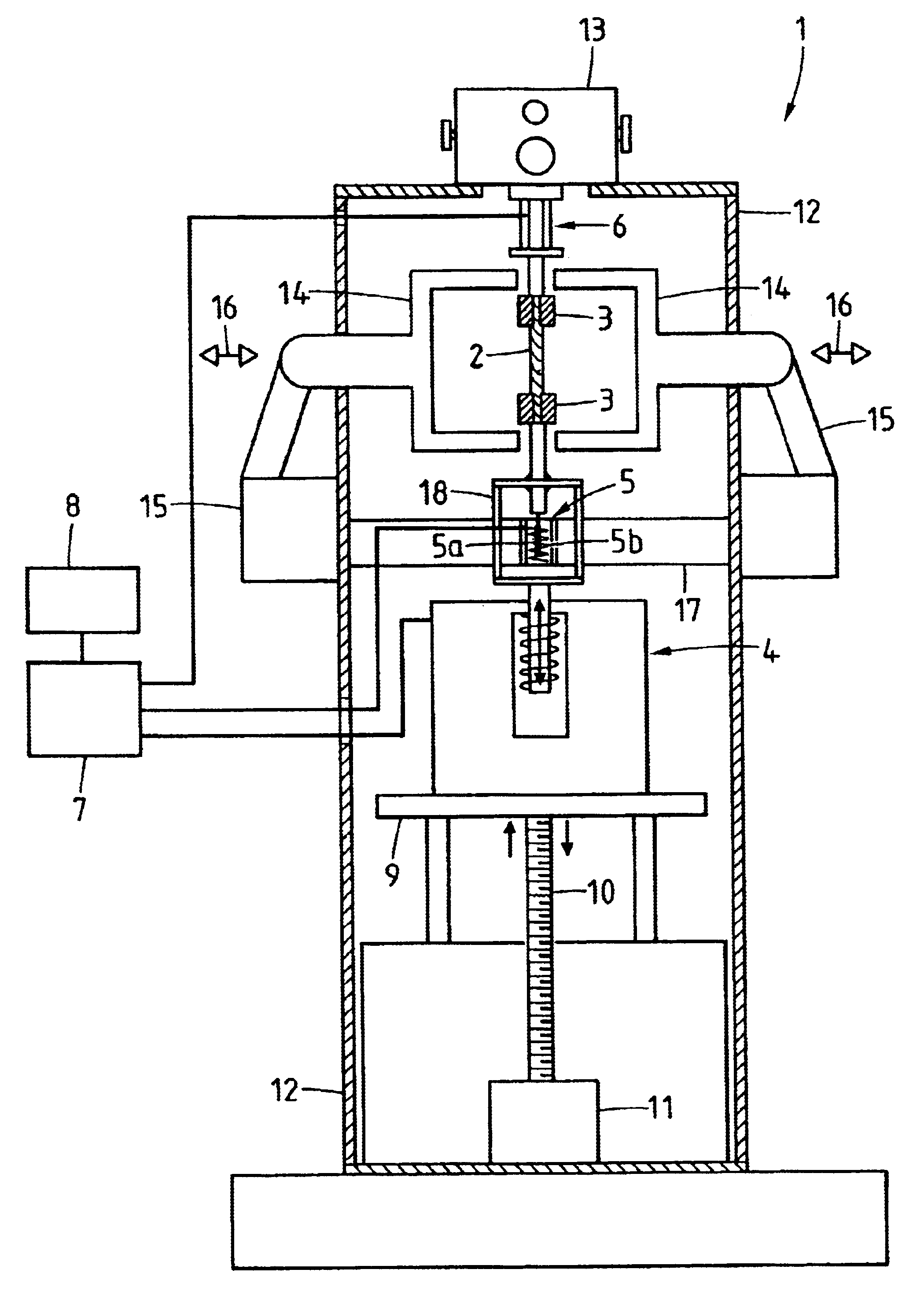
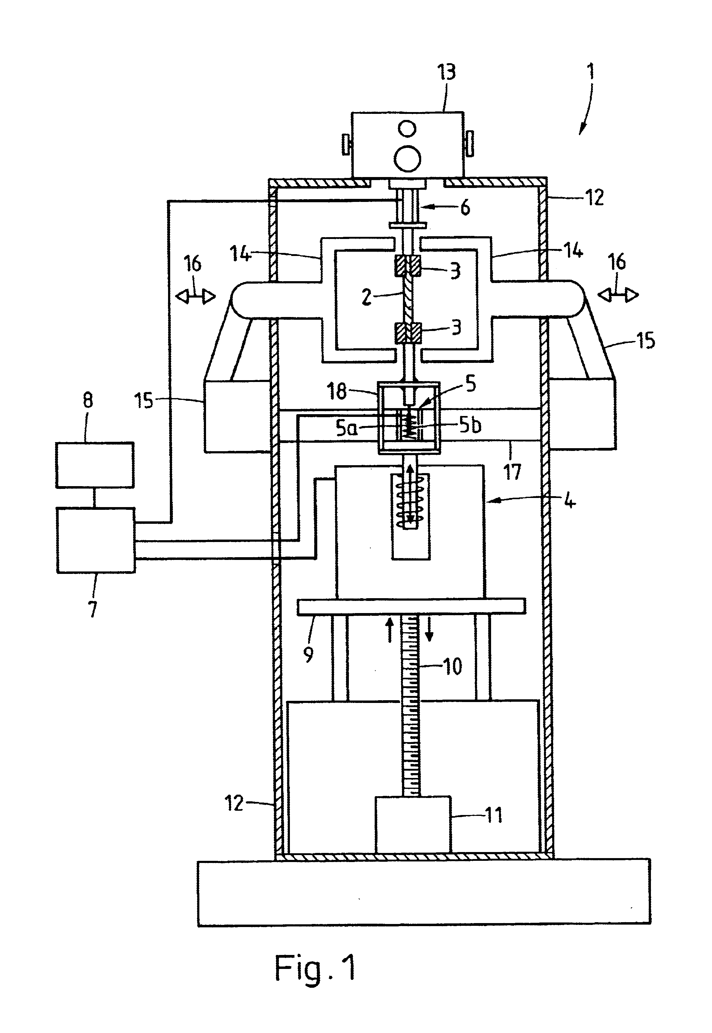
[0029]FIG. 1 illustrates an apparatus 1 for performing dynamic mechanical analyses on a test specimen 2. The specimen 2 is held by a holder device 3, and an excitation device 4 applies a static pre-tensioning force and a time-variable excitation force to the specimen. The deformation of the specimen 2 is measured by at least one displacement sensor 5. The apparatus 1 preferably includes a force sensor 6 which can measure the entire force applied to the specimen 2 or may be designed to measure only the dynamic portion of the force. The excitation device 4, the displacement sensor 5, and the force sensor 6 which may be provided in some embodiments of the apparatus are tied to a control- and data-collecting device 7 which is connected to an operating device or input / output device 8. It is considered self-evident that the displacement of the lower end of the specimen could also be transmitted through a transfer mechanism to a displacement sensor mounted in the upper part of the apparatu...


PUM

PropertyMeasurementUnit
frequencyaaaaaaaaaa
frequencyaaaaaaaaaa
frequencyaaaaaaaaaa

Abstract

In a dynamic mechanical analysis, a test specimen is coupled to an excitation device by a holder device. An excitation force made up of a static pre-tensioning force component and a time-variable force component is applied to the test specimen, and a deformation of the test specimen is measured by one or more displacement sensors. In a test phase an excitation force is applied to the test specimen, while at least one decision parameter is determined. The decision parameter is indicative of a degree of slack in the coupling of the test specimen. Based on the comparison between the decision parameter and at least one reference value it is determined whether or not the test specimen is coupled to the excitation device in a completely slack-free state, so that any measured physical values will not be subjected to errors caused by an insufficient amount of the pre-tensioning force.

Description

BACKGROUND OF THE INVENTION[0001]The invention relates to a method of performing dynamic mechanical analyses, wherein a specimen under investigation is held in a holder device and is subjected to a static pre-tensioning force and a time-variable excitation force generated by an excitation device, and wherein the deformation of the specimen is measured by means of one or more displacement sensors. The invention further relates to an apparatus for performing the method. Included in the apparatus are a controller device that directs and controls the analysis process, a holder device for holding the specimen, an excitation device that allows a static pre-tensioning force and a time-variable excitation force to be applied to the specimen, and one or more displacement sensors to measure the deformation of the specimen.[0002]Dynamic mechanical analyses (DMA) are used to determine visco-elastic material properties. To perform a dynamic mechanical analysis, the samples to be investigated are...

Claims


Application Information

Patent Timeline
Patent Type & Authority Patents(United States)
IPC IPC(8): G01N3/08G01N3/32G01N3/38G01N3/04G01N3/02G01N3/00
CPCG01N3/08G01N3/38G01N2203/0003G01N2203/0007G01N2203/0226G01N2203/0037G01N2203/005G01N2203/0208G01N2203/0222G01N2203/0017
Inventor ESSER, ULRICHHUTTER, THOMAS
Owner METTLER TOLEDO GMBH
Why Eureka
Try Eureka