Method and arrangement for determining signal degradations in the presence of signal distortions

Inactive Publication Date: 2006-04-27
SIEMENS AG
View PDF4 Cites 9 Cited by
  • Summary
  • Abstract
  • Description
  • Claims
  • Application Information

AI Technical Summary

Benefits of technology

[0010] When recording eye patterns for the purpose of determining the signal quality, a fast photodiode is used to sample synchronously the power level of the optical signal, or one of its channels. A variable delay line ensures that it is possible to make measurements not only at the center of the bit but also to the left and right of it. In this way, one obtains the overlaps in the power level graphs of many bits in a single diagram. The larger is the internal opening, the so-called eye, the better can a discriminator in the receiver distinguish between the “zeros” and “ones” which are transmitted, and the more error-free is the signal transmission. In the case of EAS (electrical amplitude sampling), the frequency distribution of the amplitude values is measured for the “zeros” and “ones” which are received, and from this the signal quality is determined. In the synchronous case, this always occurs at a fixed sampling time point. This is generally in the center of the bit.
[0021] In the case of broadband optical signals, such as in typical WDM transmission systems, a part of the spectrum, for example at a channel wavelength, is isolated before the signal is fed into the adaptive optical filter. It is advantageous if the only connection downstream from the adaptive optical filter is to a fast photodiode with a downstream module for measuring the quality parameter. The photodiode can also be integrated into the module for measuring the quality parameter. Several values of the quality parameter are saved for different settings of the adaptive optical filter's pass characteristics, and are compared with the value of the quality parameter when the adaptive optical filter allows everything to pass. By doing so, one obtains a measure of the degradation of the optical signal in terms of signal interference. The use of the adaptive filter in the optical domain is advantageous because the influence is exerted on the signal even before the photodiode (and thus before the loss of phase information), and individual effects can thus be more easily determined.
[0027] When electrical equalizers or compensators are used for determining signal degradations in the presence of signal distortions, several important advantages should be noted. First, as a basic technology these components are commercially available from a wide choice of products. The realization of an arrangement of this type in accordance with the invention is thus simple and economical. They can always be used, regardless of the type of receiver or transmission system, or the supplier.
[0029] Electrical equalizers offer a very short setting time and can, for example, be set or regulated within a few thousand bits, i.e. in less than 1 μs at 10 Gb / sec. The method in accordance with the invention thus has a high speed.

Problems solved by technology

The object of determining the signal quality and the causes of faults is a central and as-yet unsolved problem for the next generation of optical networks.
However, with this method several problems arise immediately.

Method used


Image

  • Method and arrangement for determining signal degradations in the presence of signal distortions
  • Method and arrangement for determining signal degradations in the presence of signal distortions
  • Method and arrangement for determining signal degradations in the presence of signal distortions

Examples


Embodiment Construction

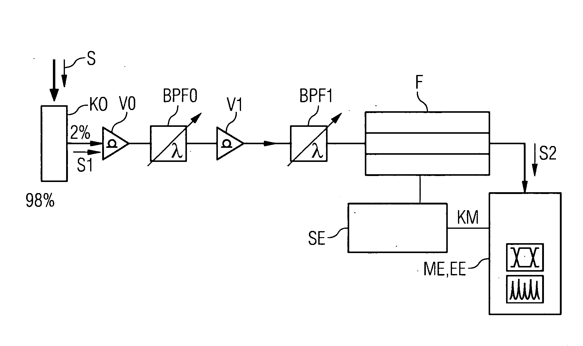
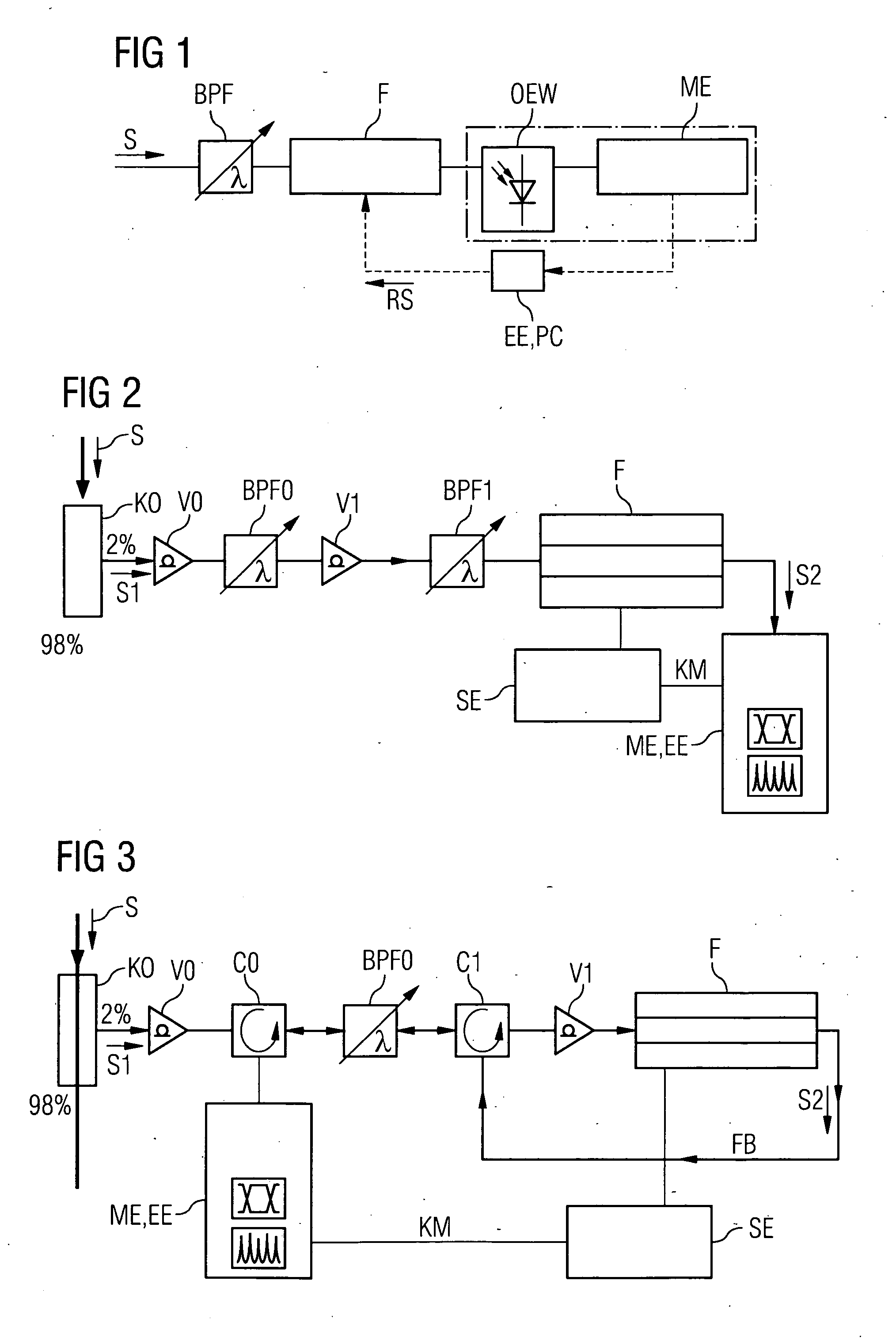
[0047]FIG. 1 describes a basic arrangement which permits a determination of signal degradations or distortions, as applicable, for an optical signal S transmitted in a transmission system. At a measurement point in the transmission system, a fraction of the optical signal S is fed to an adaptive optical filter F, and is then measured from a measurement unit ME according to a quality parameter. For the measurement unit, use is made for example of an electrical spectrum analyzer or a power meter on a bandpass filter BPF, in circuit before the adaptive optical filter F for the purpose of isolating one optical channel wavelength. For this purpose, an opto-electric converter OEW is connected between the adaptive optical filter F and the measurement unit. However, the opto-electric converter OEW is in practice often integrated into the measurement unit ME). Here, a fast photo-diode is used. The use of the adaptive filter F in the optical domain is advantageous because it exerts its influe...


PUM


Abstract

The invention relates to a method and several arrangements for determining signal degradations of an optical signal transmitted in a transmission signal in the presence of signal distortions, wherein at least one part of the optical signal is fed to an adaptive optimal or electric filter at a place of measurement in the transmission system and is subsequently measured according to one or several quality parameters. A first measurement of the quality parameter is carried out by transparent adjustment of the adaptive filter and other measurements of the quality parameters are carried out with redefined transparency properties of the adaptive optical filter which respectively have an influence upon signal distortions. As a result it is possible to analyze or to separate signal-influencing effects or groups of effects. In another embodiment of the invention, the filter parameters of an optical / electric equalizer or filter structure, which are adjusted by said analysis, are described according to optimization of the signal quality.

Description

CROSS REFERENCE TO RELATED APPLICATIONS [0001] This application is the US National Stage of International Application No. PCT / DE2003 / 002941, filed Sep. 4, 2003 and claims the benefit thereof. The International Application claims the benefits of German application No. 10246723.4 filed Oct. 8, 2002, both applications are incorporated by reference herein in their entirety.FIELD OF THE INVENTION [0002] The invention relates to a method and an arrangement for determining signal degradations in the presence of signal distortions. SUMMARY OF THE INVENTION [0003] Determination of the optical signal quality and the reasons for signal interference, preferably in the next generation of WDM networks (WDM=wavelength division multiplex), is of great importance for the operation of optical networks. Thus, for example, the qualities of the individual channels must be measured in a WDM signal which is transmitted, in order to control a so-called pre-emphasis or a tipping, as applicable, of the power...

Claims


Application Information

Patent Timeline
Patent Type & Authority Applications(United States)
IPC IPC(8): H04B10/24H04B10/2507
CPCH04B10/2507
Inventor BOHN, MARCNEUHAUSER, RICHARDWRAGE, MARC-STEFFEN
Owner SIEMENS AG
Why Eureka
Try Eureka