Balancer device for engine

a technology for balancers and engines, applied in mechanical equipment, machines/engines, auxillary lubrication, etc., can solve the problems of increasing the number of parts and the number of assembly steps, and achieve the effect of reliably supporting the balancer shaft and increasing the rigidity of the balancer housing

Inactive Publication Date: 2005-04-19
HONDA MOTOR CO LTD
View PDF15 Cites 20 Cited by
  • Summary
  • Abstract
  • Description
  • Claims
  • Application Information

AI Technical Summary

Benefits of technology

[0023]With the above arrangement, the bearing portions and the gear-accommodating portion protruding from the upper surface of the balancer housing are connected to each other by the projection and hence, the rigidity of the balancer housing can be increased to reliably support the balancer shafts.

Problems solved by technology

The balancer device described in Japanese Patent Application Laid-open No. 2001-140985 does not have a cover member for covering the clearance in the balancer housing and hence, there is a possibility that the oil splashed up in a crankcase by the crankshaft may enter the balancer housing through the clearance.
However, if the clearance is covered as described above, a special cover member is disadvantageously required, resulting in increases in the number of parts and the number of assembling steps.

Method used


Image

  • Balancer device for engine
  • Balancer device for engine
  • Balancer device for engine

Examples


first embodiment

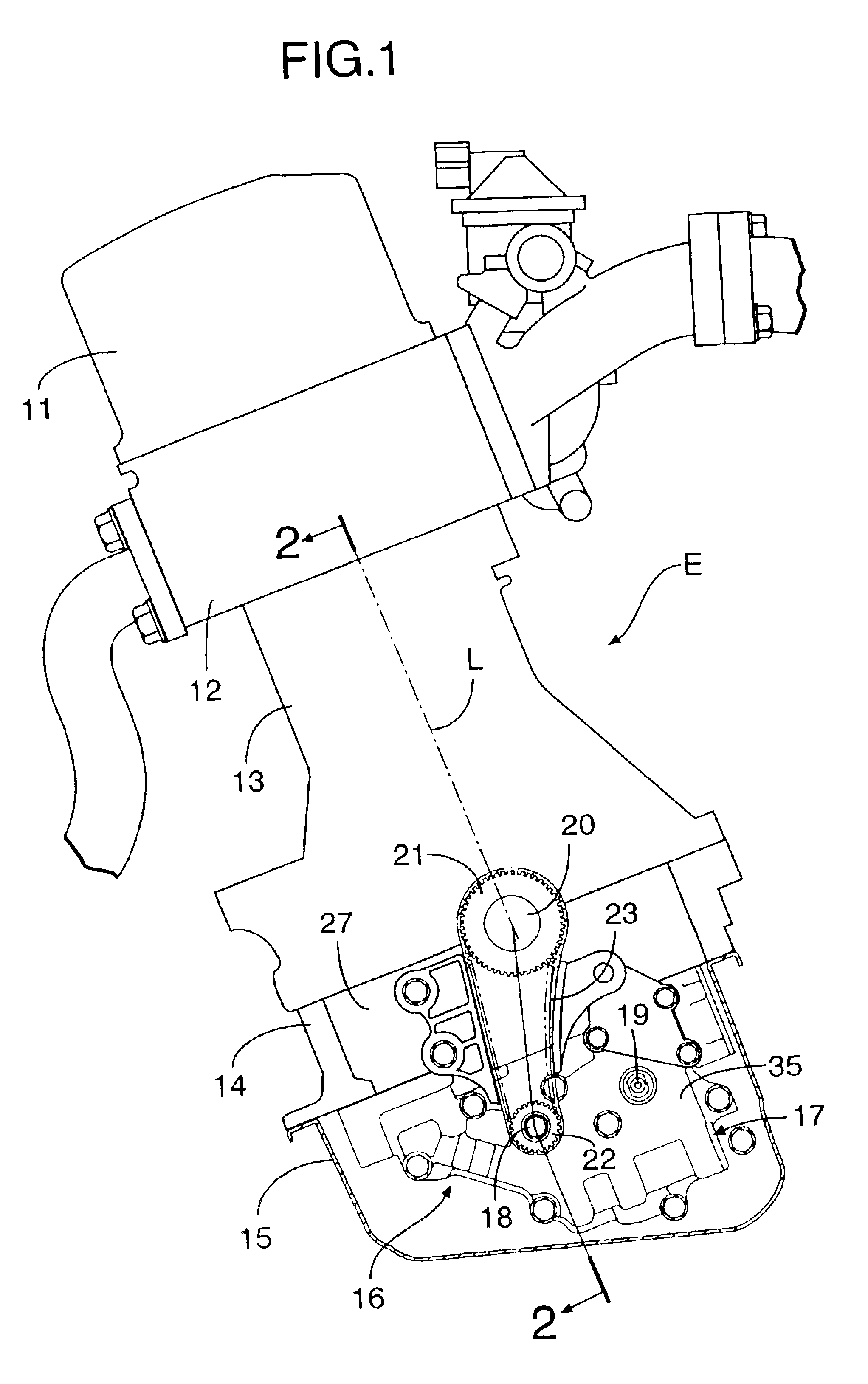
[0047]The present invention will now be described by way of the first embodiment with reference to FIGS. 1 to 12.

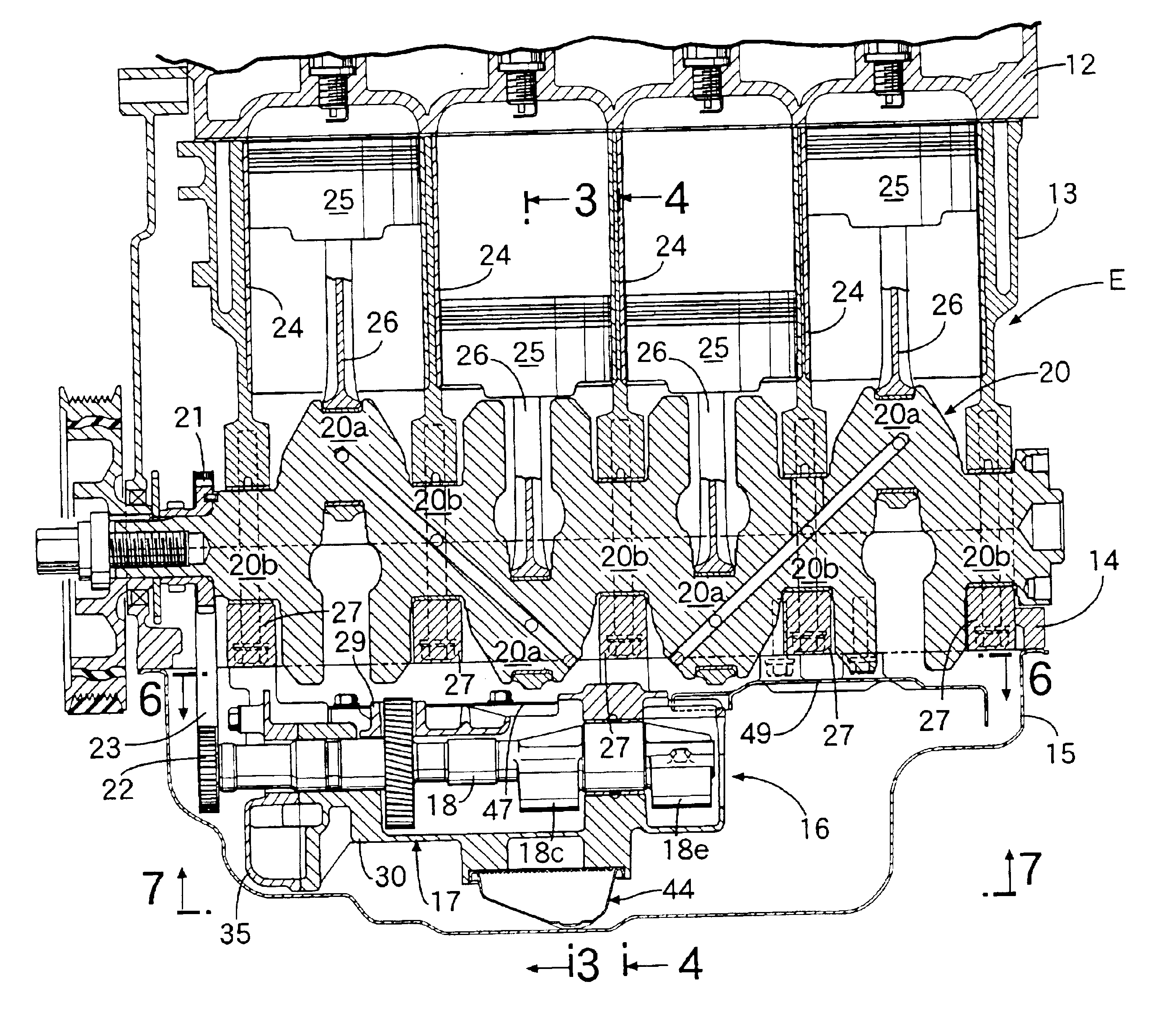
[0048]As shown in FIG. 1, the contour of an in-line 4-cylinder engine E for a vehicle is formed by disposing a head cover 11, a cylinder head 12, a cylinder block 13, a lower block 14 and an oil pan 15 in the named order from top to bottom. A cylinder axis L is inclined toward an exhaust side (leftwards as viewed in FIG. 1) with respect to a vertical direction. A secondary balancer device 16 fixed to a lower surface of the lower block 14 and accommodated in the oil pan 15 includes a driving balancer shaft 18 and a follower balancer shaft 19 supported in a balancer housing 17. A sprocket 21 mounted at an end of a crankshaft 20 supported between the cylinder block 13 and the lower block 14 and a sprocket 22 mounted at an end of the driving balancer shaft 18 are connected to each other by an endless chain 23.

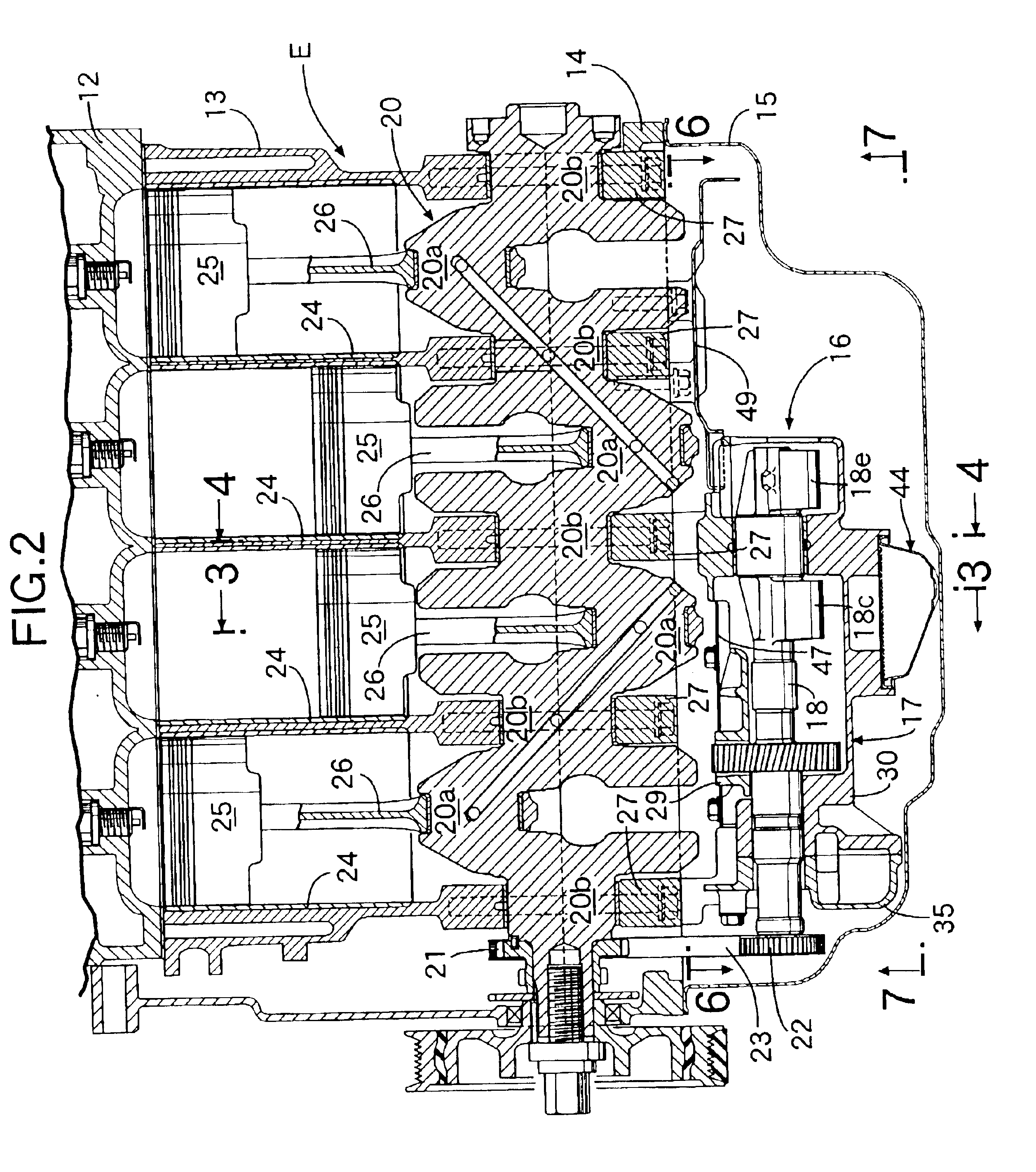
[0049]As shown in FIGS. 2 to 5, four pistons slidably received in f...

second embodiment

[0066]the present invention will now be described with reference to FIG. 13.

[0067]In the second embodiment, a first baffle plate 47 and a second baffle plate 48 of the first embodiment are integrally connected to each other by a connection 51 to form a single angular U-shaped baffle plate 52, leading to a reduction in the number of parts. The shapes and functions of the first baffle plate 47 and the second baffle plate 48 are the same as in the first embodiment.

[0068]In the first embodiment shown in FIG. 6, a clearance γ (see FIGS. 6 and 7) is provided between the end edge of the angular U-shaped notch 49c in the third baffle plate 49 and the end edge of the balancer housing 17, but if the end edge of the angular U-shaped notch 49c in the third baffle plate 49 is overlapped on the end edge of the balancer housing 17 by a distance δ, the oil from above the third baffle plate 49 can be prevented from entering the balancer housing through the openings 17a and 17b provided in the end of...

third embodiment

[0069]the present invention will now be described with reference to FIG. 14.

[0070]In the first embodiment of the present invention shown in FIG. 6, the angular U-shaped notch 49c is defined between the pair of cover portions 49a and 49b of the third baffle plate 49, but in the third embodiment, a pair of bores 49d, 49d is defined between the cover portions 49a and 49b and opposed to a pair of openings 29d, 29d which the second balancer weights 18e and 19e face. With the third embodiment, the bores 49d, 49d exhibit the same function as that of the notch 49c in the first embodiment, whereby the rigidity of the cover portions 49a and 49b can be increased by T-shaped connecting walls 49e and 49f surrounding the bores 49d, 49d to inhibit the generation of the vibration further effectively, while reducing the weight of the third baffle plate 49 and reducing the vertical dimension of the engine E.


PUM


Abstract

A balancer housing of a balancer device disposed to face an oil pan below a crankshaft of an engine, includes oil discharge bores for discharging an oil accumulated in the balancer housing with the rotation of balancer weights. The oil discharge bores are covered by baffle plates for inhibiting the turbulence of a surface of the oil stored in the oil pan. Thus, it is possible to inhibit the entrance of the oil into the balancer housing through the oil discharge bores without provision of a special cover member for covering the oil discharge bores.

Description

BACKGROUND OF THE INVENTION[0001]1. Field of the Invention[0002]The present invention relates to a balancer device for an engine, including a balancer housing disposed below a crankshaft to face an oil pan.[0003]2. Description of the Related Art[0004]Such balancer devices for engines are known from Japanese Patent Application Laid-open No. 2001-140985 and Japanese Utility Model Application Laid-open No.1-61415.[0005]In the balancer device described in Japanese Patent Application Laid-open No. 2001-140985, an oil accumulated within the balancer housing is raked up by a rotating balancer, and such oil is discharged to the outside through a clearance defined in a side of the balancer housing. In the balancer device described in Japanese Utility Model Application Laid-open No. 1-61415, an upper portion of a discharge bore provided in an upper surface of the balancer housing for discharging a blow-by gas is covered with a cover member, whereby the discharge bore is prevented from being c...

Claims


Application Information

Patent Timeline
Patent Type & Authority Patents(United States)
IPC IPC(8): F02B67/04F16F15/22F16F15/26
CPCF16F15/267F02B67/04
Inventor HASHIMOTO, HISAYUKIOKAZAKI, KAZUHITO
Owner HONDA MOTOR CO LTD
Why Eureka
Try Eureka