Actuator for driving rotary valve actuator and valve device with the actuator

a technology of actuator and rotary valve, which is applied in the direction of valve operating means/releasing devices, transportation and packaging, and service pipe systems, etc., can solve the problems of poor workability and the inability to separate operation costs

Inactive Publication Date: 2005-04-19
YAMATAKE HONEYWELL CO LTD
View PDF22 Cites 67 Cited by
  • Summary
  • Abstract
  • Description
  • Claims
  • Application Information

AI Technical Summary

Benefits of technology

[0014]Since the holding portion and the engaging element that is held by the holding portion so as to be rotatable up to the prescribed angle are designed to be mounted on the actuator side, the valve gear requires that only the locking element is mounted on the valve side thereof. This makes it possible to utilize valves of various sizes and kinds for the valve gear according to the present invention.

Problems solved by technology

The detaching operation costs work, especially in case that the actuator and the valve are installed near an indoor ceiling, for example.
However, if the prescribed or greater axial external force is mistakenly applied to a housing of the actuator, the actuator comes off the valve.
Also in another embodiment illustrated in FIGS. 4-9 of Japanese Patent Application Kokai No. 2000-193129, any tools are not required at the time of the attachment or detachment of the actuator, but a nut has to be rotated many times, so that the workability is poor.

Method used


Image

  • Actuator for driving rotary valve actuator and valve device with the actuator
  • Actuator for driving rotary valve actuator and valve device with the actuator
  • Actuator for driving rotary valve actuator and valve device with the actuator

Examples


first embodiment

[0030]Hereinafter, a valve gear comprising a rotary valve actuator for activating a rotary valve, according to the present invention, will be explained with reference to drawings.

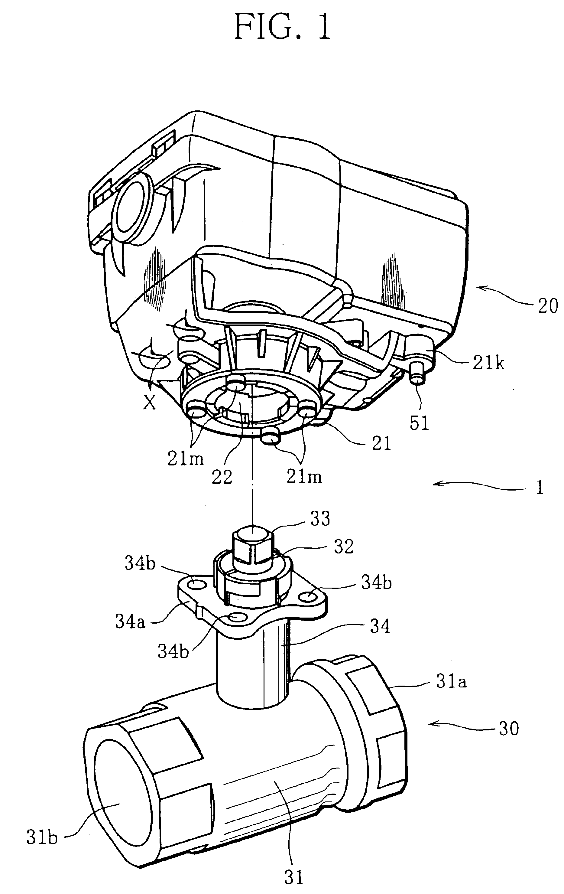
[0031]A valve gear 1 including the rotary valve actuator (hereinafter simply referred to as “actuator”) according to the first embodiment of the present invention comprises, as illustrated in FIG. 1, an actuator 20 having, on the output shaft side thereof, a resin-made yoke (holding member) 21 and a resin-made engaging element (rotating member) 22; and a ball valve 30 having a resin-made locking element 32 that is fixed on the operation shaft side and adapted to be engaged with the engaging element 22 of the actuator 20.

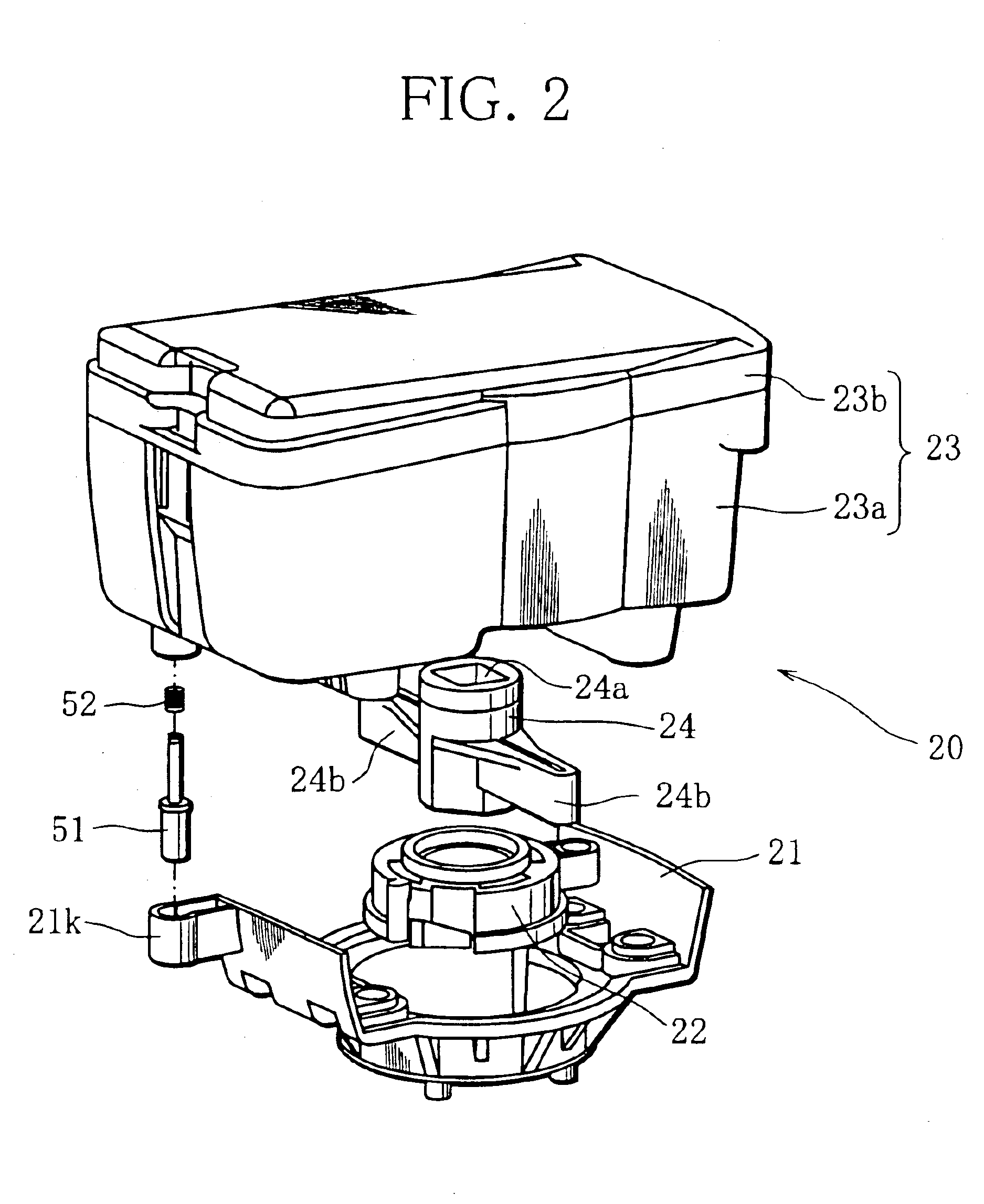
[0032]As shown in FIG. 2, the actuator 20 comprises a housing 23 including a case 23a and a cover 23b, the yoke 21 mounted on a bottom surface of the housing 23 to couple the housing 23 onto the ball valve 30, the engaging element 22 housed in the yoke so as to be rotatable within a prescrib...

second embodiment

[0072]Hereinafter, a valve gear according to the present invention will be described.

[0073]Structure elements identical to those of the above-described embodiment are denoted by corresponding reference numerals, and detailed explanations thereof will be omitted.

[0074]As illustrated in FIG. 9, a valve gear 2 including an actuator according to the second embodiment of the present invention comprises an actuator 120 having a resin-made yoke (holding portion) 121 and a resin-made engaging element 122 on an output shaft side, and a ball valve 130 having a resin-made locking element 132 fixed on an operation shaft side and adapted to be engaged with the engaging element 122.

[0075]An output shaft 120s for activating a rotary valve protrudes from a substantially central portion of a lower surface of the actuator 120 and is adapted to be coupled through a joint 124 onto an operation shaft 133 projecting from an end portion of the valve 130. A release clutch operation shaft 152 protrudes from...


PUM


Abstract

A valve gear includes a valve (30), which controls a flow rate of a fluid and an opening of which is determined according to a rotational position of a valve element, an actuator (20) for providing a rotational force to a rotary valve shaft that changes the opening of the valve (30), and attaching/detaching means. The attaching/detaching means includes a locking element (32) formed at its prescribed positions with locking concave/convex portions and an engaging element (22) formed at its prescribed positions with engaging concave/convex portions. The locking element (32) and the engaging element (22) are relatively rotatable around the rotary valve shaft up to a prescribed angle, and prevent the actuator (20) from coming off the valve (30) at an engaging position where the engaging concave/convex portions and the locking concave/convex portions are engaged with one another, and allow the actuator (20) and the valve (30) to be detached from each other at a disengaging position.

Description

[0001]This application is a U.S. National Phase Application under 35 USC 371 of International Application PCT / JP01 / 00544 filed Jan. 26, 2001.TECHNICAL FIELD[0002]The present invention relates to a rotary valve actuator for actuating a valve, which is mounted on the valve and provides a rotational force to change the valve opening, and a valve gear comprising the same. More specifically, the present invention relates to a rotary valve actuator capable of being easily attached to / detached from a valve, and a valve gear comprising the same.BACKGROUND ART[0003]A rotary valve actuator for activating a rotary valve is known that is mounted on the valve and provides a rotational force that changes the valve opening.[0004]A conventional rotary valve actuator is shown in FIG. 4 of Japanese Utility Model Kokai Publication No. Hei 6-1951, for instance. This actuator has an output shaft adapted to be coupled through a joint to an operation shaft of an opening / closing valve at chamfered portions...

Claims


Application Information

Patent Timeline
Patent Type & Authority Patents(United States)
IPC IPC(8): F16K31/04
CPCF16K31/041Y10T137/8275Y10T137/7256F16K31/04
Inventor HAIKAWA, TOMOYUKISEKINE, KOUICHI
Owner YAMATAKE HONEYWELL CO LTD
Why Eureka
Try Eureka