Electrical unit with a connector for a loop through conductor

a technology of electrical units and conductors, applied in the direction of coupling device details, coupling device connections, contact members penetrating/cutting insulation/cable strands, etc., can solve the problem of relative large, and achieve the effect of little spa

Inactive Publication Date: 2005-04-19
SIEMENS AG
View PDF12 Cites 6 Cited by
  • Summary
  • Abstract
  • Description
  • Claims
  • Application Information

AI Technical Summary

Benefits of technology

[0010]An embodiment of the present invention provides an electrical device with which, in spite of the use of insulation displacement technology, through-wiring may be achi

Problems solved by technology

A typical disadvantage of insulation displacement terminals is that they are rel

Method used


Image

  • Electrical unit with a connector for a loop through conductor
  • Electrical unit with a connector for a loop through conductor
  • Electrical unit with a connector for a loop through conductor

Examples


Embodiment Construction

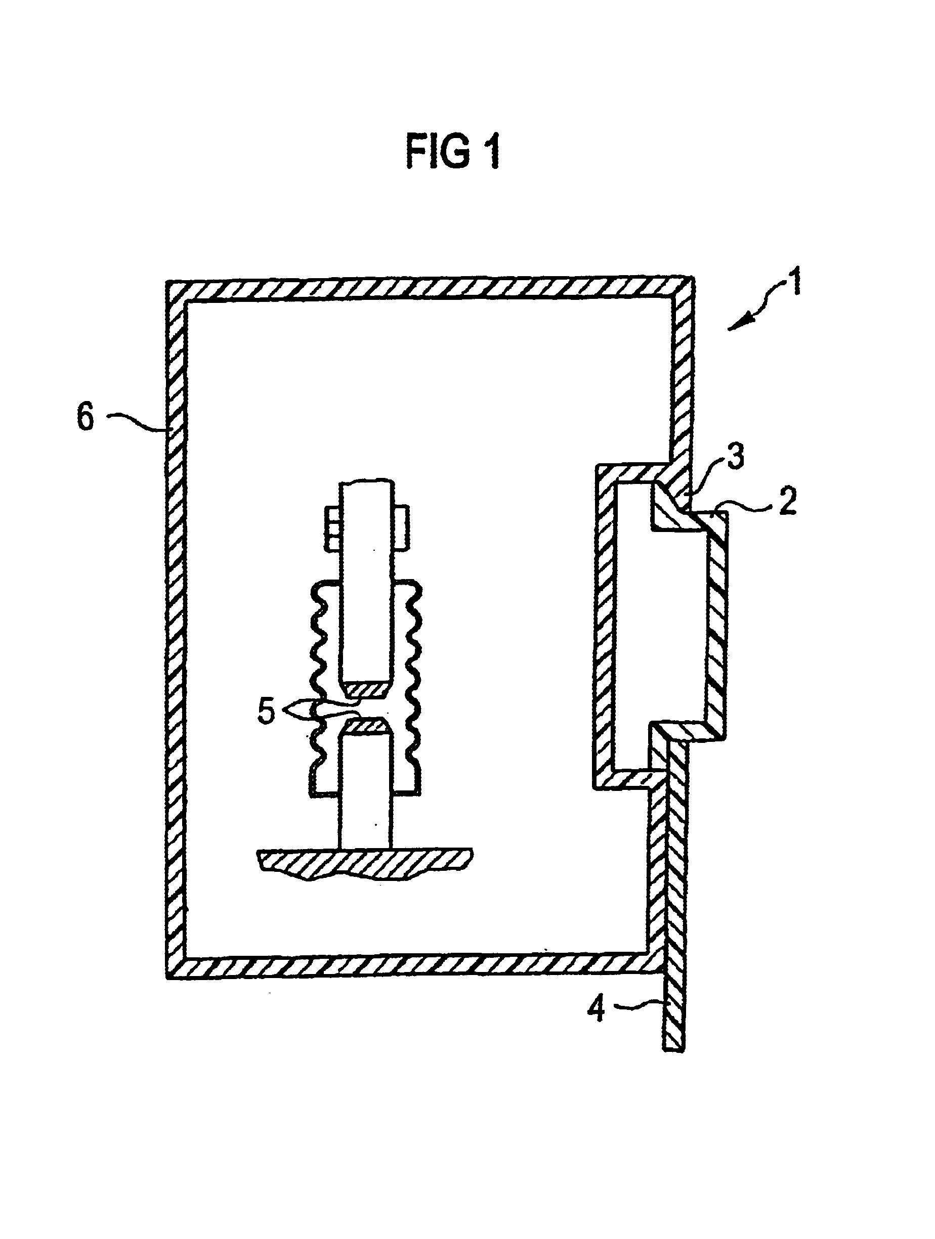
[0031]According to FIG. 1, a mounting face of an electrical device can be fastened by way of a mounting device 1 to a supporting element 2. According to FIG. 1, the supporting element 2 is a mounting rail. The mounting device includes a hook element 3 and a spring-loaded bolt 4 so that the electrical device can be snapped onto the mounting rail 2.

[0032]In principle, the electrical device can be of any nature. According to the exemplary embodiment, it is an electromagnetic switching device, e.g. as a contactor. This is indicated in FIG. 1 by a (vacuum) contact 5, shown symbolically.

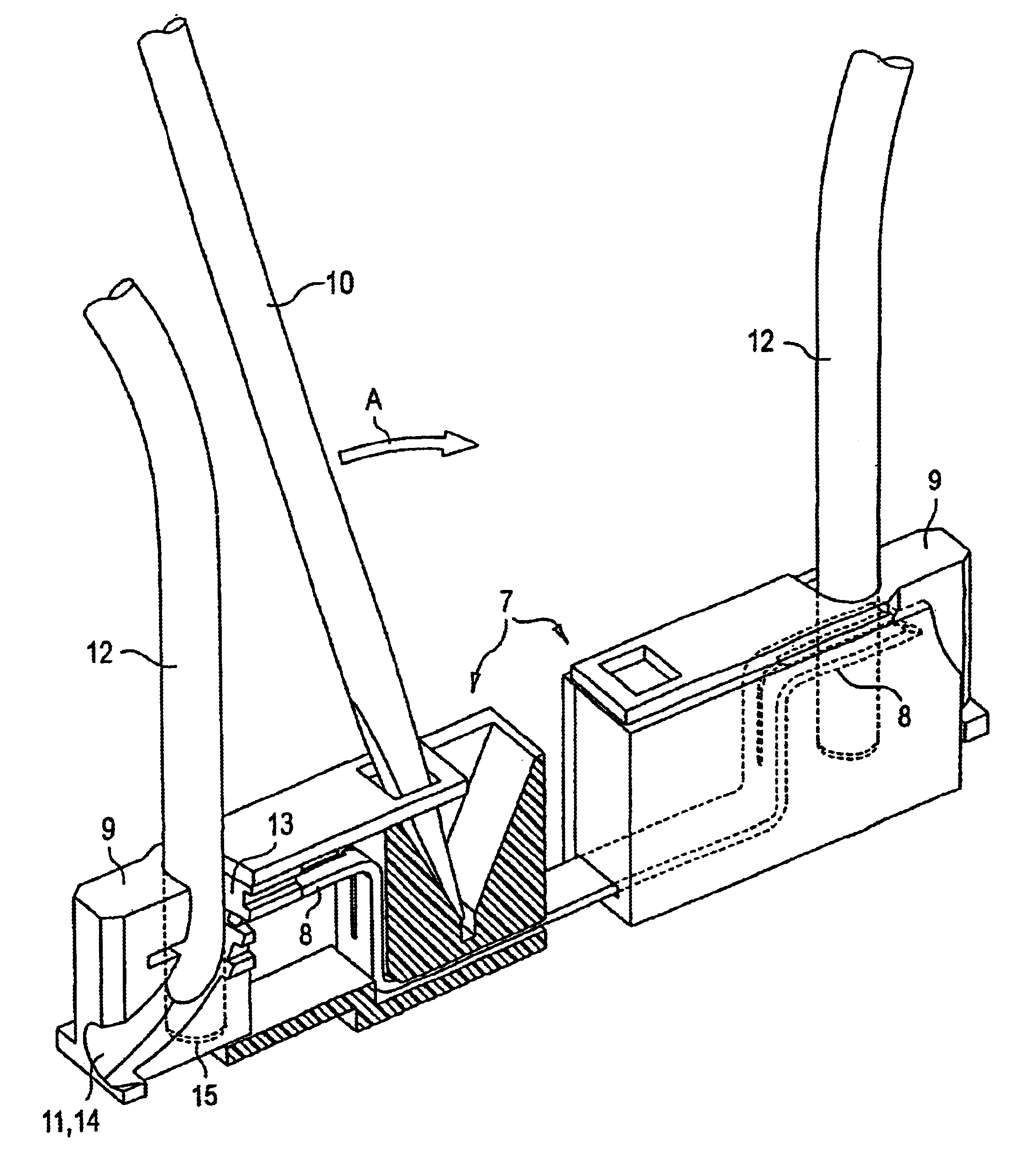
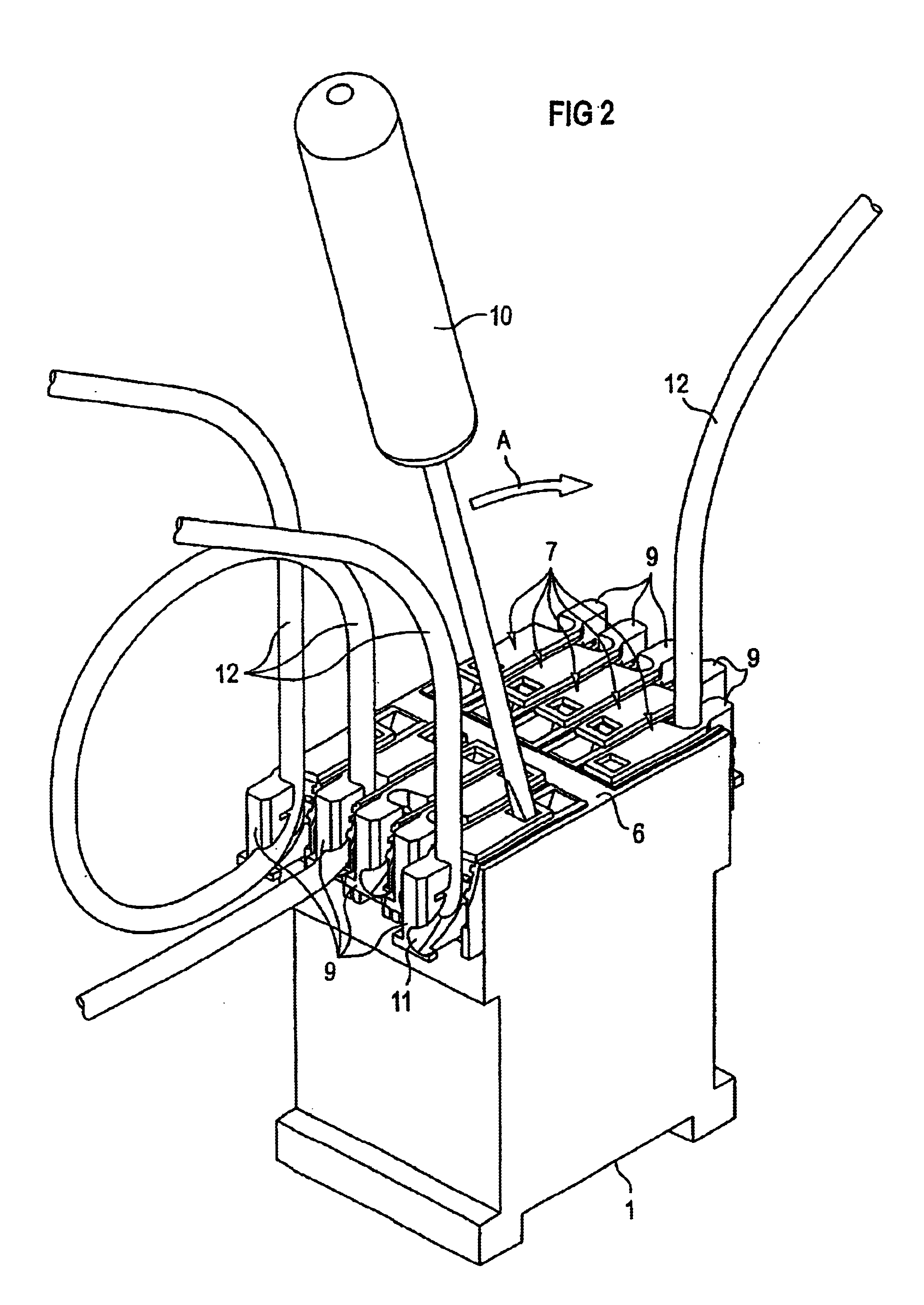
[0033]According to FIG. 2, two rows of insulation displacement terminal devices are arranged on a control face 6 opposite the mounting face. The insulation displacement terminal devices 7 are arranged next to one another within the rows, the rows themselves being arranged opposite one another. The insulation displacement terminal devices 7 are all designed to be the same as one another.

[0034]Only one of th...


PUM


Abstract

The invention relates to an electrical unit comprising a mounting device for fastening the unit to a supporting element, e.g. to a mounting rail, and at least one insulation piercing connecting device provided with an insulation piercing element and with a holding element. The insulation piercing element and holding element can move in relation to one another. When the unit is fastened to the supporting element, a conductor can be inserted into the holding element. This enables aid conductor to be looped through the holding element. The conductor can be clamped by transferring the insulation piercing element and holding element into a closed position.

Description

[0001]This application is the national phase under 35 U.S.C. §371 of PCT International Application No. PCT / DE01 / 02973 which has an International filing date of Aug. 3, 2001, which designated the United States of America and which claims priority on German Patent Application number DE 100 39 961.4 filed Aug. 16, 2000, the entire contents of which are hereby incorporated herein by reference.FIELD OF THE INVENTION[0002]The present invention generally relates to an electrical device with a mounting device for fastening the device to a supporting element, such as a mounting rail.BACKGROUND OF THE INVENTION[0003]Units of this kind are known, e.g., in the form of contractors, relays, circuit breakers, field bus devices and many others.[0004]Furthermore, so-called insulation displacement terminals are generally known, by way of which conductors can be clamped without previously removing the conductor insulation.[0005]A typical disadvantage of insulation displacement terminals is that they a...

Claims


Application Information

Patent Timeline
IPC IPC(8): H01R4/24H01R9/24
CPCH01R4/2433H01R9/2491
Inventor BRANDL, WOLFGANGDONHAUSER, PETERFISCHER, ALFREDNIEBLER, LUDWIG
Owner SIEMENS AG
Why Eureka
Try Eureka