Stent assembly

Inactive Publication Date: 2005-04-19
NESSTENT
View PDF6 Cites 2 Cited by
  • Summary
  • Abstract
  • Description
  • Claims
  • Application Information

AI Technical Summary

Benefits of technology

[0006]The present invention seeks to provide a stent assembly that filters and traps embolic material,

Problems solved by technology

When this material travels downstream, it can cause serious complications.
For example, loose embolic material released within the ascending aorta, the aortic arch, or the carotid arteries may travel downstream to the brain, possibly causing stroke, which can lea

Method used


Image

  • Stent assembly
  • Stent assembly

Examples


Example

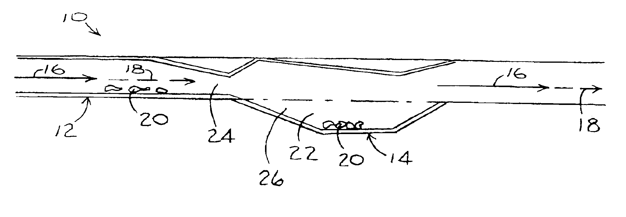
[0029]Reference is now made to FIG. 1, which illustrates a stent assembly 10 constructed in accordance with an embodiment of the present invention.

[0030]Stent assembly 10 preferably includes an upstream portion 12 and a downstream portion 14 in fluid communication with upstream portion 12. Both upstream and downstream portions 12 and 14 are adapted for a blood stream 16 to flow therethrough. Blood stream 16 may include a non-embolic flow portion 18 including substances, such as but not limited to, erythrocytes, leucocytes and plasma, and embolic material 20 disposed in the blood stream. Embolic material 20 may have entered the blood stream 16 by loosening from the blood vessel wall. Downstream portion 14 preferably comprises a trapping region 22 for trapping therein embolic material 20, as is described more in detail hereinbelow. Trapping region 22 may be in an upstream portion of downstream portion 14. Upstream portion 12 is adapted to modify a flow characteristic of embolic materi...


PUM


Abstract

A stent assembly including an upstream portion adapted to modify a flow characteristic of embolic material disposed in a blood stream flowing through the upstream portion, and a downstream portion in fluid communication with the upstream portion and adapted for the blood stream to flow therethrough, the downstream portion including a trapping region for trapping therein the embolic material. The downstream portion may extend from the upstream portion, or alternatively, may be distanced from the upstream portion.

Description

[0001]This application claims the benefit of provisional application No. 60 / 239,923 filed Oct. 13, 2000FIELD OF THE INVENTION[0002]The present invention relates generally to stent assemblies and particularly to a stent assembly adapted to filter and trap embolic material.BACKGROUND OF THE INVENTION[0003]Stenosis within arteries and other blood vessels may be treated by permanently or temporarily introducing a stent into the stenosed region to open the lumen of the vessel. The stent may be introduced into the desired blood vessel using known percutaneous or transluminal methods. A catheter, having the stent securely crimped thereon, may be directed to the region of the blood vessel being treated. The catheter may be positioned such that the stent is centered across the stenosed region. Balloon inflation may then be used to expand the stent radially, thereby engaging the stenosed material. As the stent expands, the material is forced outward, dilating the lumen of the blood vessel. Du...

Claims


Application Information

Patent Timeline
IPC IPC(8): A61F2/06A61F2/01A61F2/82
CPCA61F2/01A61F2/82A61F2/013A61F2002/068
Inventor ISRAEL, HENRY M.
Owner NESSTENT
Why Eureka
Try Eureka