Memory repeater

a repeater and memory technology, applied in the direction of unauthorized memory use protection, memory adressing/allocation/relocation, instruments, etc., can solve the problems of limiting the maximum speed and bandwidth of the system, affecting the performance of the bus, etc., and achieve the effect of improving the performance of the high-speed data bus

Inactive Publication Date: 2005-04-19
MICRON TECH INC
View PDF10 Cites 125 Cited by
  • Summary
  • Abstract
  • Description
  • Claims
  • Application Information

AI Technical Summary

Benefits of technology

The present invention is about a way to improve the performance of a high-speed data bus, like a memory bus, by using selectively activated receiver and driver pairs. This allows for data communication on specific segments of the bus, while disconnecting other segments to create a more efficient and reliable connection between system components. The technical effect of this invention is better performance and reliability of high-speed data buses.

Problems solved by technology

The technical problem addressed in this patent is the need to improve the performance of memory bus systems and other data bus systems, by reducing signal reflections caused by electrical stubs and degradation of signal integrity, to allow for high speed operation with minimal degradation of signal integrity due to bus reflections.

Method used


Image

  • Memory repeater
  • Memory repeater
  • Memory repeater

Examples


Embodiment Construction

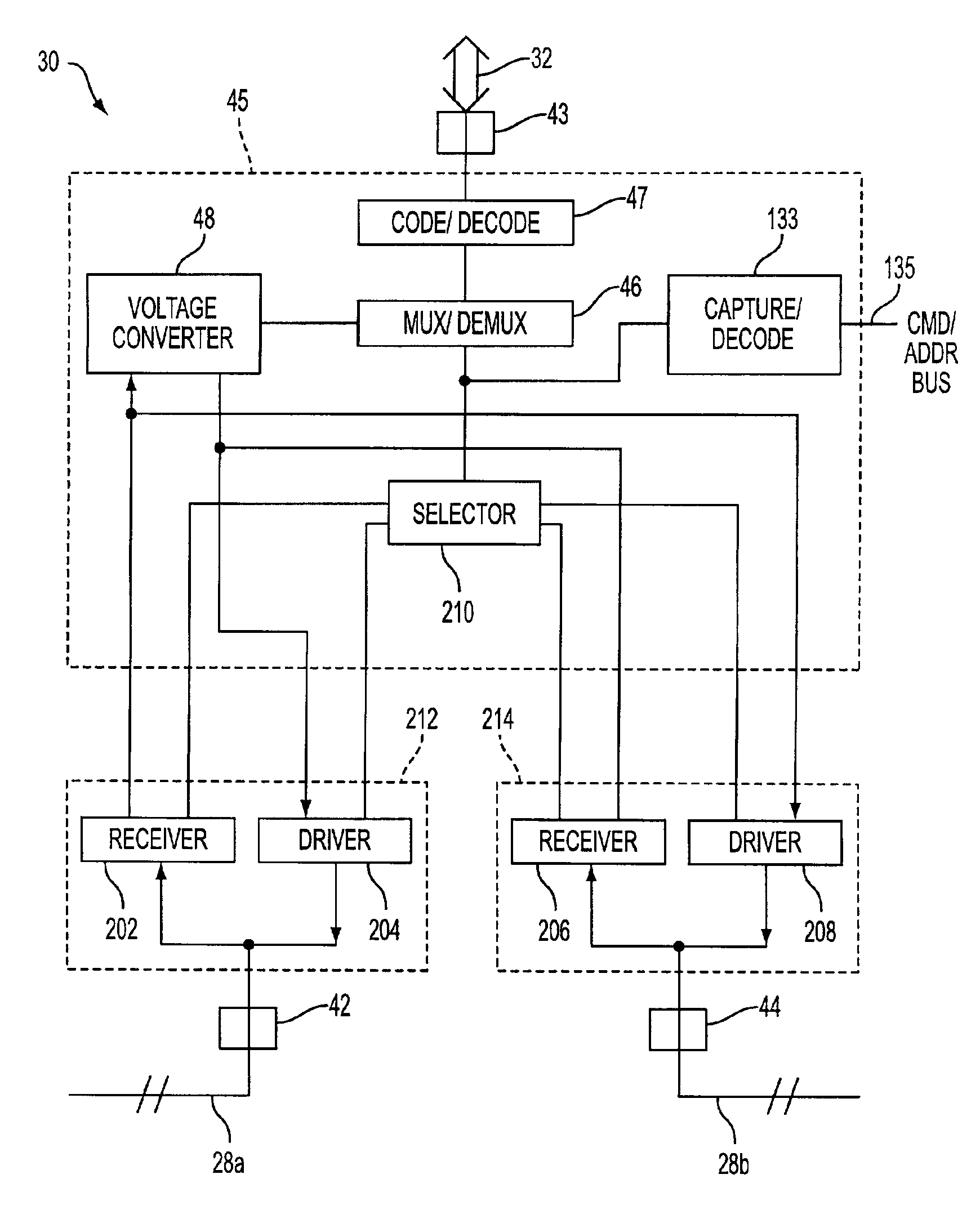
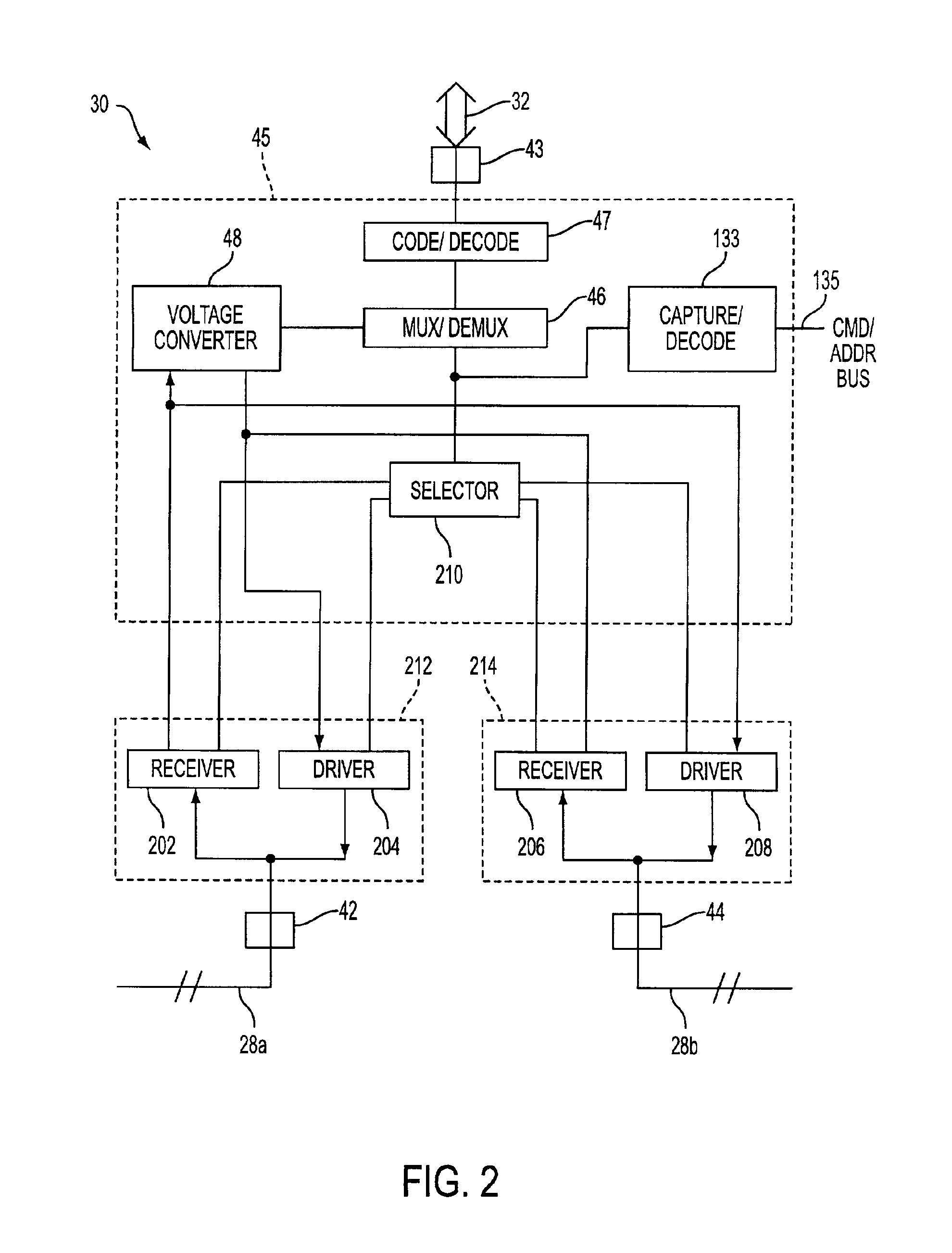
[0025]The invention provides a bus system and associated devices which may be used to interconnect data input / output devices. While the invention is described below with reference to a memory system, including memory devices as representative data input / output devices, it should be understood that the invention may be used with any type of data input / output device. Likewise, it should be understood that the memory controller described in the context of a memory system may be a bus controller for use with other data input / output devices.

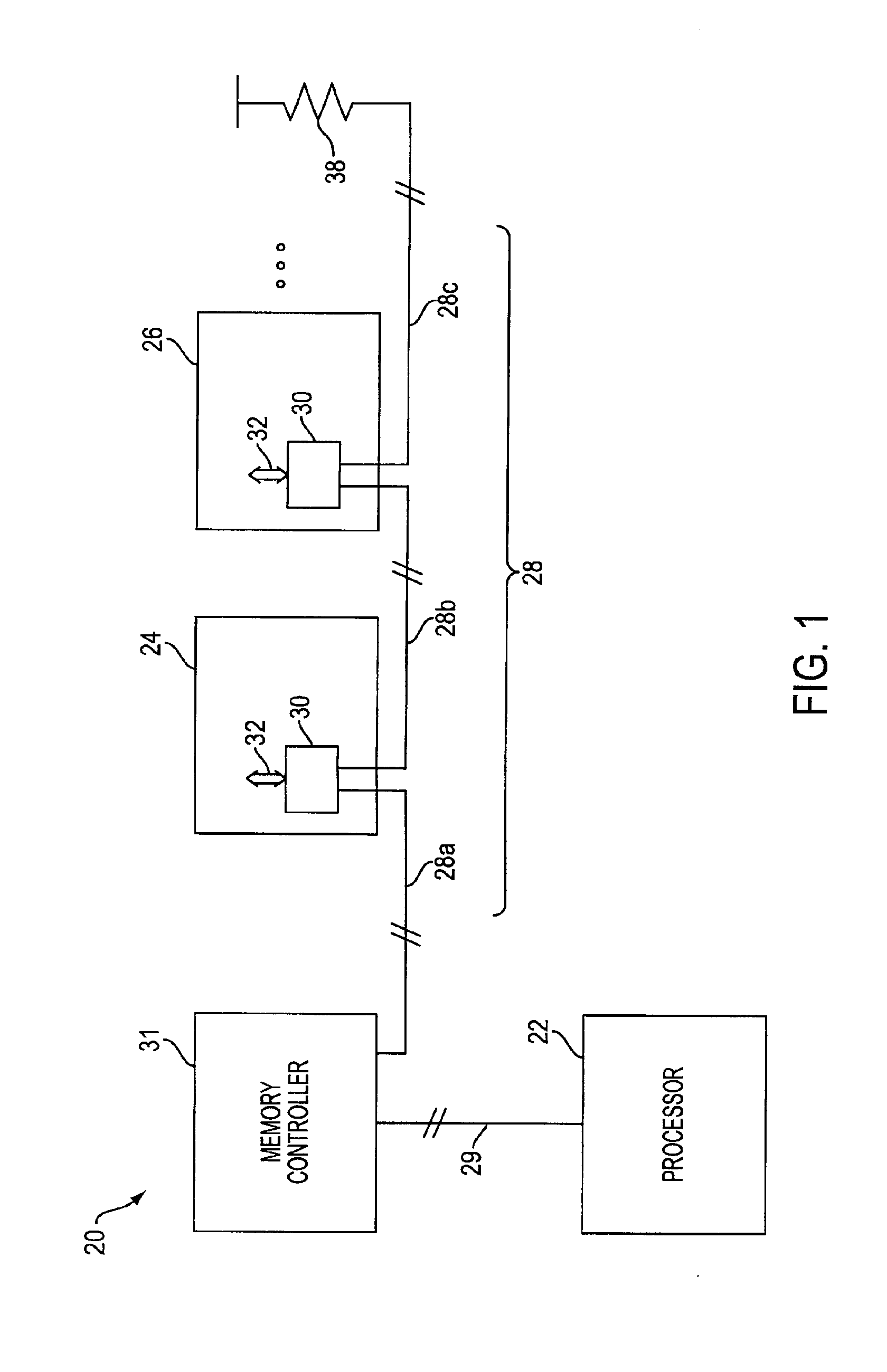
[0026]Referring to FIG. 1, an exemplary processor system 20 including a memory subsystem is illustrated employing a high speed bus system and receiver / driver pairs in accordance with the invention. The processor system 20 includes several data input / output devices, which take the form of memory modules 24, 26, connected to a memory controller 31 by a segmented data bus 28, and a processor 22 connected to the memory controller 31 via a conventional bus...


PUM


Abstract

A method and associated apparatus are provided for improving the performance of a high speed data bus, such as a memory bus, using selectively activated receiver and driver pairs. Each receiver and driver pair may be selectively activated to permit data communication on a segment of the high speed data bus coupled to the activated receiver and driver pair. Each receiver and driver pair may also be deactivated, thereby disconnecting at least a respective segment of the high speed data bus, so that communicating system components may be connected in a substantially stubless environment.

Description


Claims


Application Information

Patent Timeline
Owner MICRON TECH INC
Why Eureka
Try Eureka