Roller spacing device

a technology of rolling pins and rollers, applied in the direction of electrographic process apparatus, instruments, corona discharge, etc., can solve the problems of defective image generation, fatal influence of rolling pins on images, and failure to achieve desired effects of rolling pins, etc., and achieve high viscosity

a technology of rolling pins and rollers, applied in the direction of electrographic process apparatus, instruments, corona discharge, etc., can solve the problems of defective image generation, fatal influence of rolling pins on images, and failure to achieve desired effects of rolling pins, etc., and achieve high viscosity

US6882813B2Inactive Publication Date: 2005-04-19S PRINTING SOLUTION CO LTD

Image

  • Roller spacing device
  • Roller spacing device
  • Roller spacing device

Examples


Embodiment Construction

[0043]Reference will now be made in detail to the embodiments of the present invention, examples of which are illustrated in the accompanying drawings, wherein like reference numerals refer to like elements throughout. The embodiments are described below in order to explain the present invention by referring to the figures.

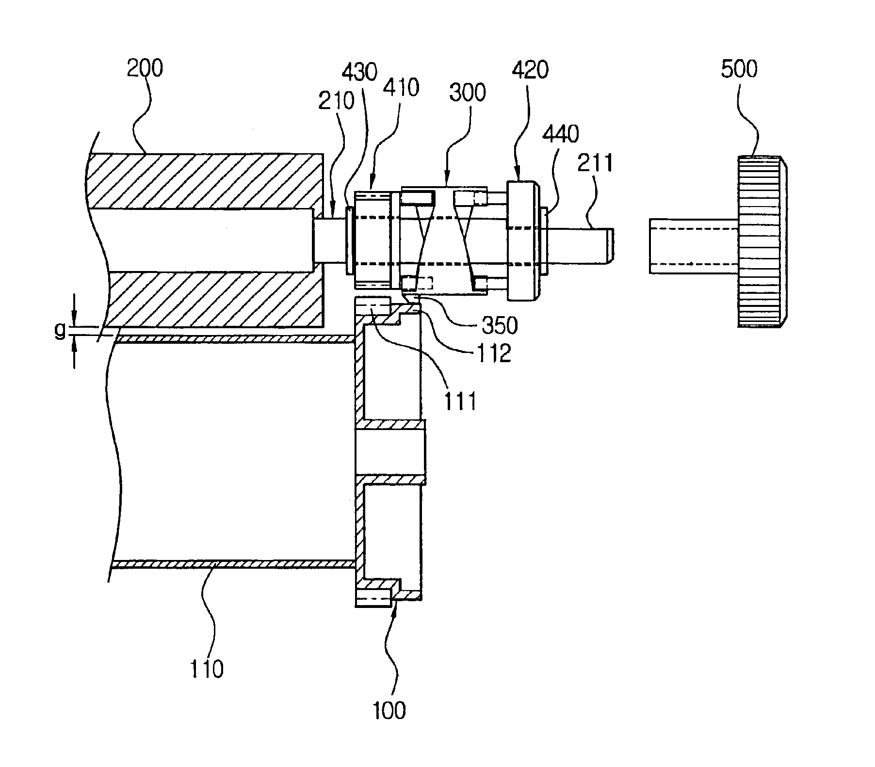
[0044]With reference to FIG. 3, reference numeral 100 indicates an OPC drum or a photosensitive medium functioning as a first roller member, 200 indicates a developing roller functioning as a second roller member, 300 indicates a spacing member, and 400 indicates a shifting unit moving the spacing member 300.

[0045]As shown in FIG. 3, the OPC drum 100 and the developing roller 200 are designed to closely contact and rotate under a given pressure by a pressing means (not shown) for the developing roller. The OPC drum 100 is provided with a driving gear 110 to drive the OPC drum. The driving gear 110 is provided with a gear portion 111 and a step portion 112 on its o...


PUM


Abstract

A roller spacing device roller mechanisms having rollers in close contact under a given pressure to separate first and second rollers by a constant distance to keep the rollers from touching when roller mechanisms are not used for a long period of time. The roller spacing device comprises a spacing member shiftably mounted between first and second positions on a shaft having a partial D-cut portion and associated with one of the roller members to be separated. The spacing member has a spacing nose overlapped in the second position with an outer circumferential surface of a driving gear connected to the other roller member to separate the first roller member from the second roller member by the constant distance; and a shifting unit shifting the spacing member between first and second positions on the shaft. With this construction, the first and second roller members are separated by a constant distance to keep each roller from touching when the roller mechanism is not driven for a long period of time so as to solve several problems which may be generated when the roller members are in contact under a given pressure for a long period of time.

Description

CROSS-REFERENCE TO RELATED APPLICATIONS[0001]This application claims the benefit of Korean Application No. 2002-42667, filed Jul. 19, 2002, in the Korean Intellectual Property Office, the disclosure of which is incorporated herein by reference.BACKGROUND OF THE INVENTION[0002]1. Field of the Invention[0003]The present invention relates to a roller spacing device to separate rollers by a constant distance so as to keep the rollers from touching each other. In particular, the roller spacing device is used in an image forming system having roller mechanisms which rotate in close contact under a given magnitude of pressure in an operating relationship between a photosensitive medium and a developing roller, between a photosensitive medium and a transferring roller, or between a photosensitive medium and a charging roller, and functions to separate the rollers by a constant distance so as to keep the rollers from touching each other when roller mechanisms are not used for a period of tim...

Claims


Application Information

Patent Timeline
19 Apr 2005
Publication
US6882813B2
IPC
G03G15/08; G03G15/00
CPC
G03G15/0813; G03G15/00
Inventors
LEE, HYUN-CHEOL