
Sensor and method of measuring mass flow non-intrusively

a sensor and mass flow technology, applied in the field of mass flow sensors, can solve the problems of pressure drop, application cannot tolerate intrusion of sensors, power consumption of sensor probes in flow stream may exceed the capacity of power sources,

Inactive Publication Date: 2005-04-26
ROSEMOUNT AEROSPACE
View PDF4 Cites 38 Cited by
  • Summary
  • Abstract
  • Description
  • Claims
  • Application Information

AI Technical Summary

Problems solved by technology

Some applications can not tolerate an intrusive sensor, i.e. a sensor which has at least one probe penetrating the wall of the flow tube.
In addition, in those applications in which the power source may be limited, power consumption of a sensor probe in the flow stream may exceed the capacity of the power source.
Moreover, disposing an intrusive probe into the flow stream will produce a pressure drop that may undesirably limit the flow of the medium through the tube.

Method used


Image

  • Sensor and method of measuring mass flow non-intrusively
  • Sensor and method of measuring mass flow non-intrusively
  • Sensor and method of measuring mass flow non-intrusively

Examples


Embodiment Construction

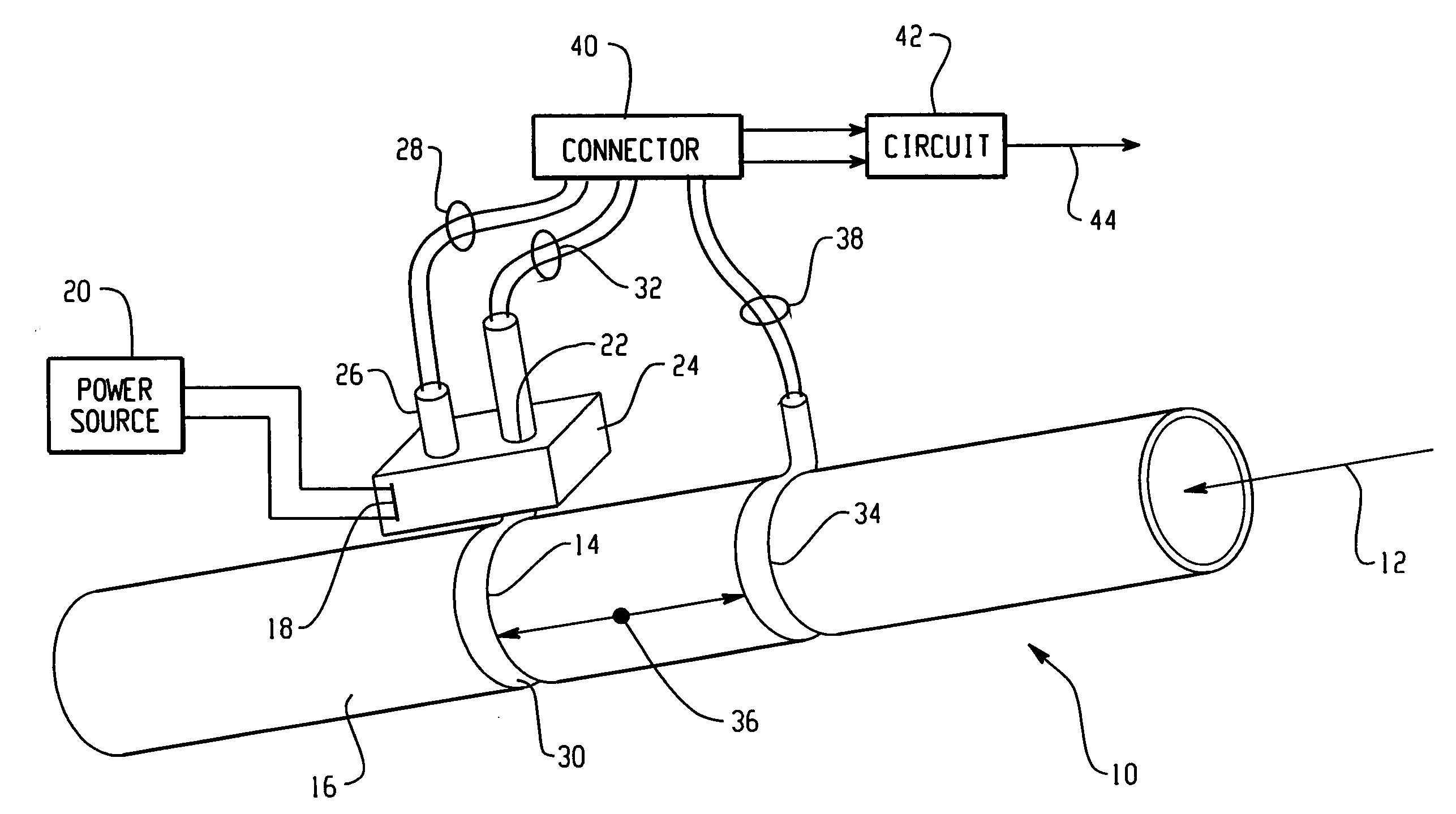
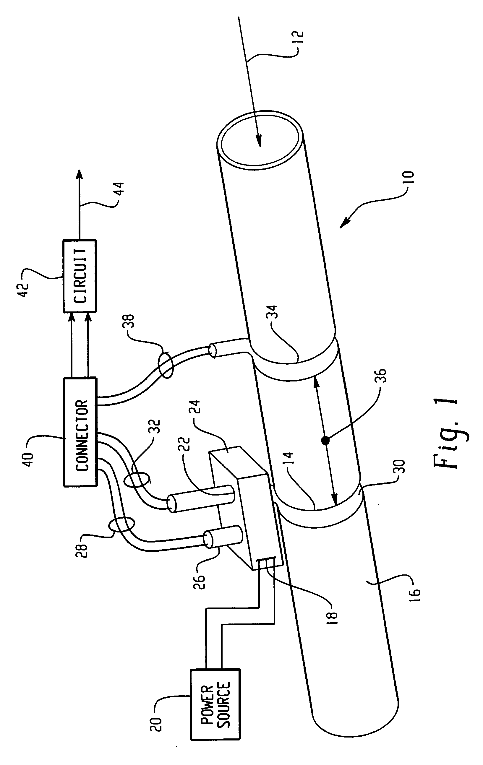
[0012]A non-intrusive mass flow sensor suitable for embodying the principles of the present invention is shown in the illustration of FIG. 1. Referring to FIG. 1, a flow tube 10 is provided to contain the flow of a medium, which may be a gas or a liquid, for example, therethrough in the direction of the arrow 12. In the present example, the flow tube 10 is made of stainless steel, but it is understood that the present invention will apply to other materials as well. A probe 14 having a predetermined length is disposed along an external wall 16 of the flow tube 10. In the present embodiment, the probe 14, which may be a metal sheathed thermocouple housing, for example, is wrapped about the circumference of the external wall 16. The probe 14 may be rendered in thermal contact with the external wall 16 by brazing the probe 14 to the wall 16, for example. It is understood that there may be other ways of rendering the probe 14 in thermal contact with the wall 16 without deviating from th...


PUM


Abstract

A non-intrusive sensor for measuring mass flow of a medium flowing through a tube comprises: a probe having a predetermined length disposed along an external wall of the tube; a heater for heating the probe at a first point along the length thereof; a first temperature measuring device disposed at the first point for measuring a temperature of the probe and for generating a first signal Th representative thereof; a second temperature measuring device disposed at a second point along the length of the probe for measuring another temperature of the probe and for generating a second signal Tt representative thereof; a third temperature measuring device disposed along the external wall of the tube a distance away from the probe for measuring an ambient temperature and for generating a signal Ta representative thereof; and circuitry coupled to the first, second and third temperature measuring devices for generating a mass flow signal based on a ratio of temperature differential signals (Th−Ta) / (Tt−Ta). A counterpart method is also disclosed.

Description

BACKGROUND OF THE INVENTION[0001]The present invention is related to mass flow sensors, in general, and more particularly, to a sensor and method of non-intrusively measuring mass flow of a medium flowing through a tube.[0002]Intrusive mass flow sensors of the thermal type generally involve disposing a heated probe through a wall of the tube and into the flow stream of the medium. The mass flow is measured by virtue of its relation to the convection heat transfer coefficient that is related to the thermal gradient measured at two points along the length of the probe, preferably at the base and tip of the probe. One example of such an intrusive mass flow sensor is provided in the U.S. Pat. No. 6,487,904, issued Dec. 3, 2002, entitled “Method and Sensor For Mass Flow Measurement Using Probe Heat Conduction” and assigned to the same assignee as the instant application.[0003]Some applications can not tolerate an intrusive sensor, i.e. a sensor which has at least one probe penetrating th...

Claims


Application Information

Patent Timeline
IPC IPC(8): G01F1/684G01F1/688G01F1/699
CPCG01F1/6888G01F1/6847
Inventor MYHRE, DOUGLAS C.
Owner ROSEMOUNT AEROSPACE
Learn More