

Center bearing assembly including a support member containing a rheological fluid
- Summary
- Abstract
- Description
- Claims
- Application Information
AI Technical Summary
Benefits of technology
Problems solved by technology
Method used
Image

Examples
Embodiment Construction
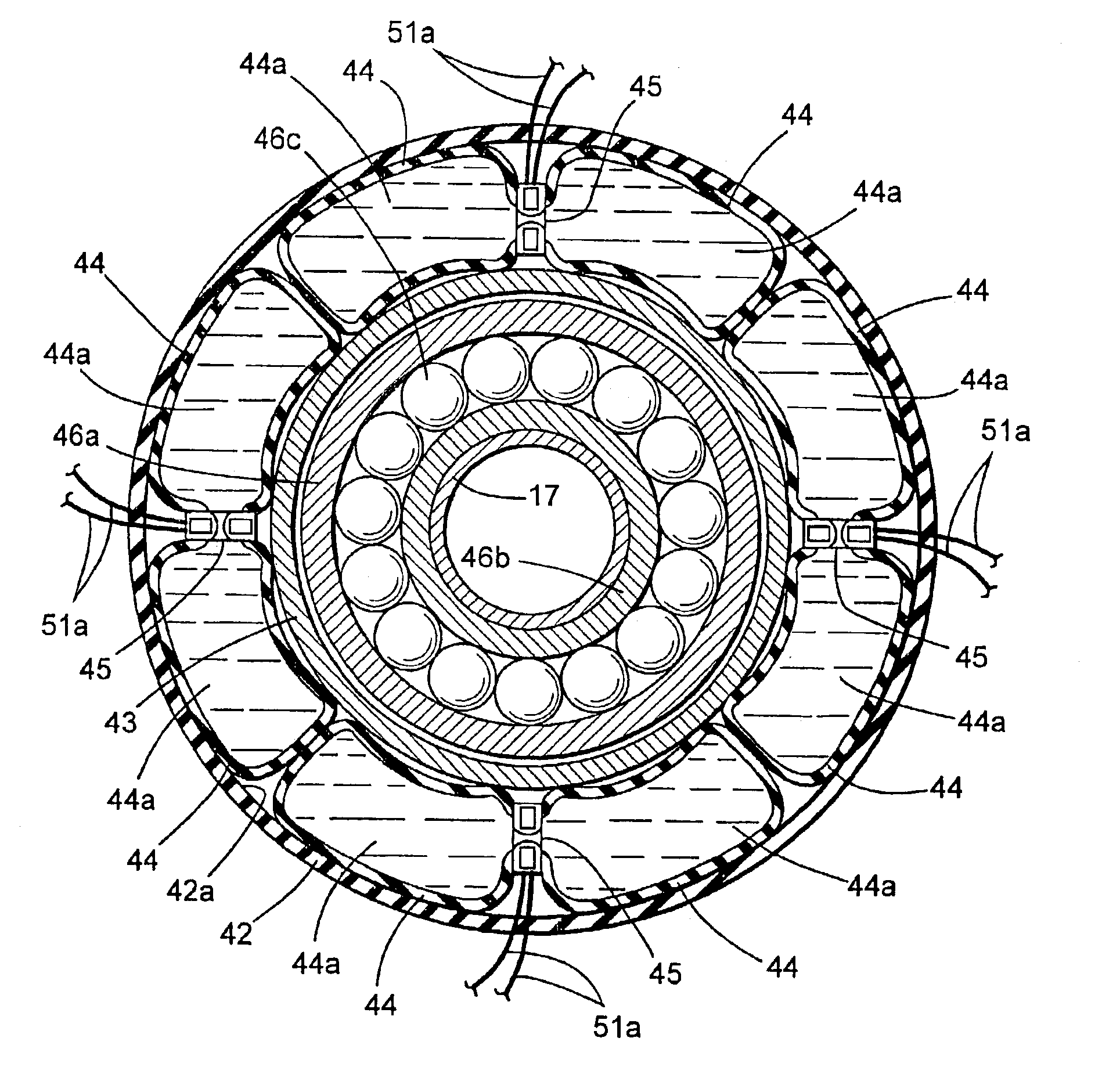
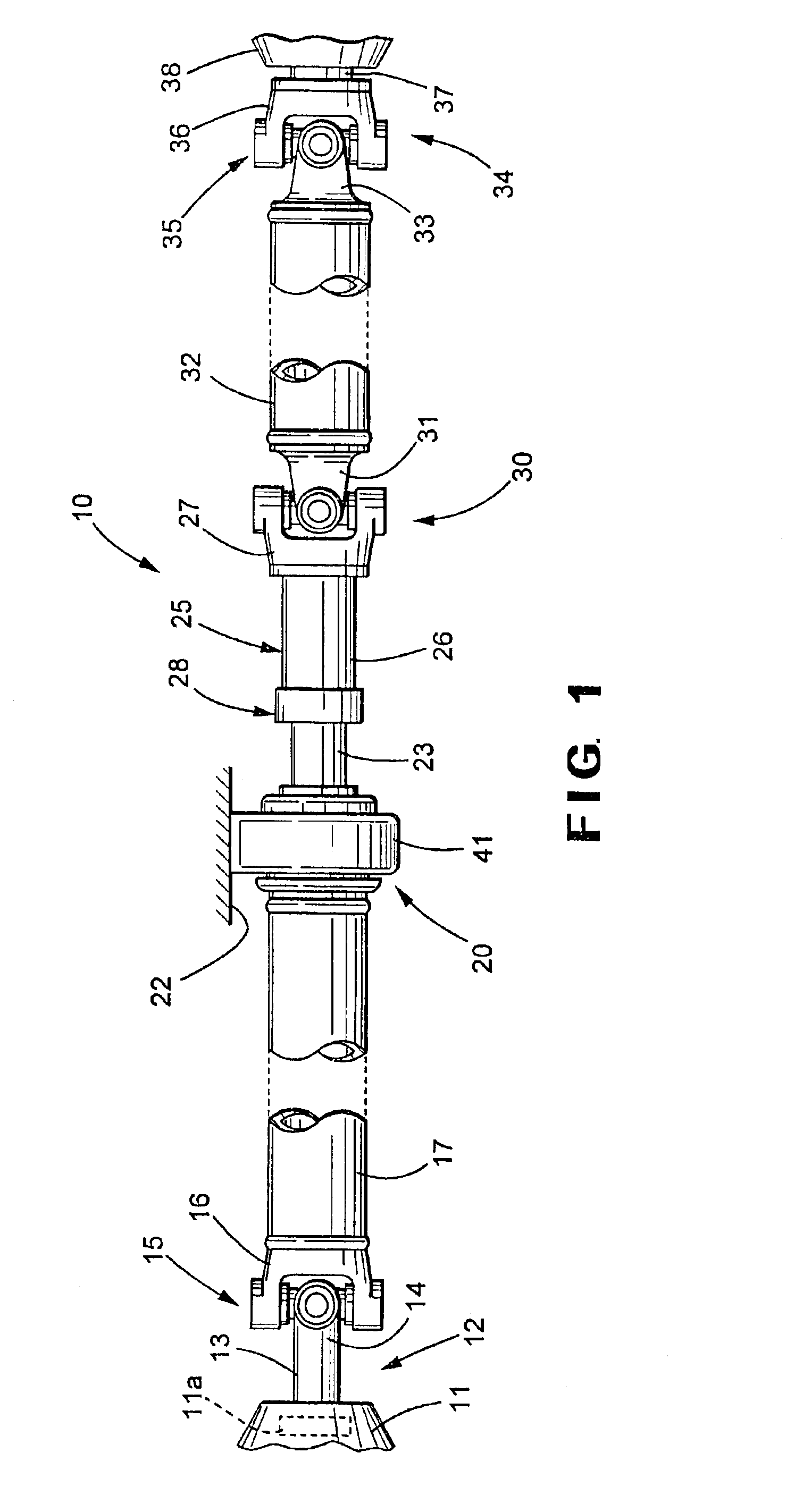
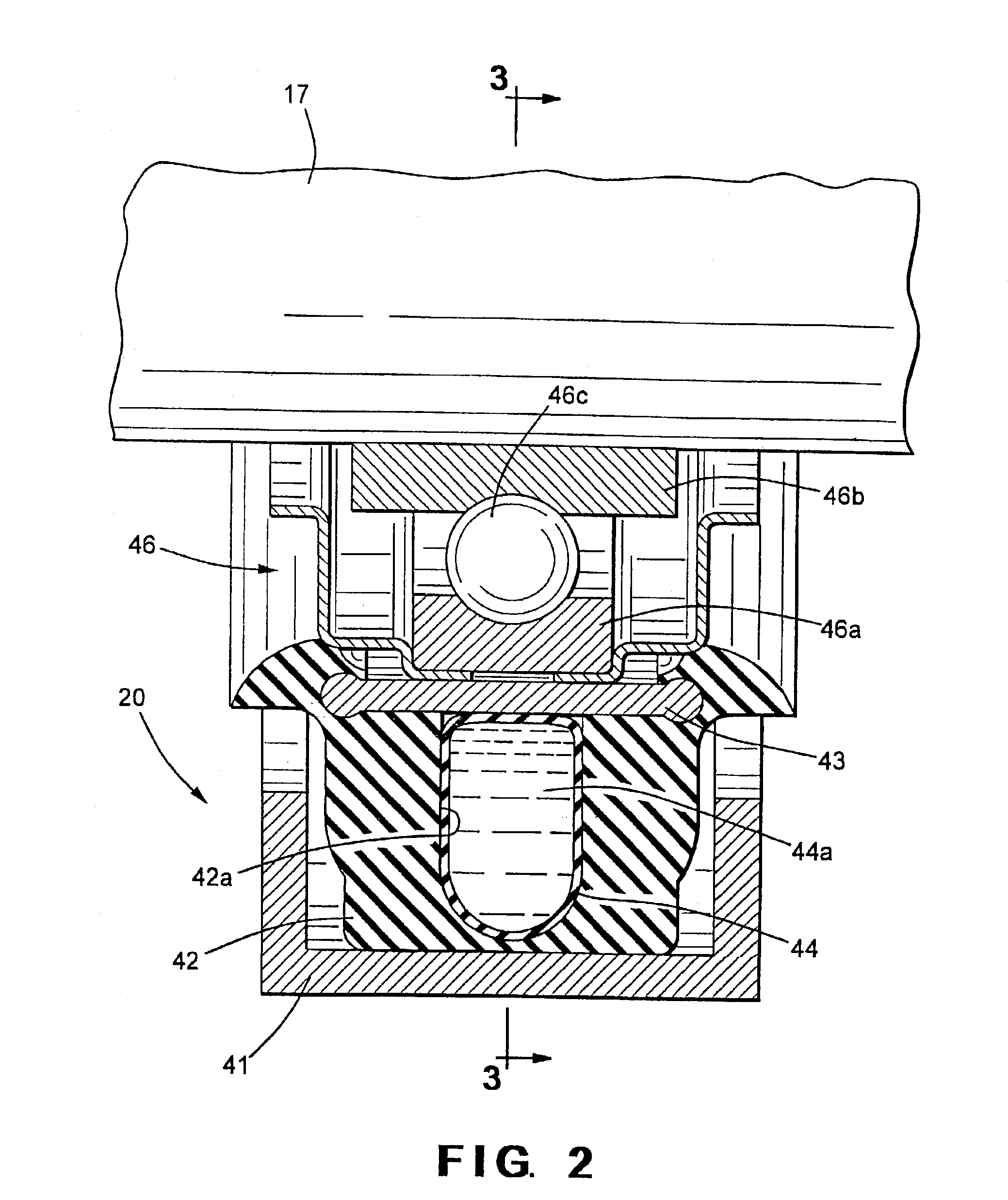
[0017]Referring now to the drawings, there is illustrated in FIG. 1 a drive train system, indicated generally at 10, for a vehicle that is adapted to transmit rotational power from an engine / transmission assembly 11 to a plurality of driven wheels (not shown). The illustrated drive train system 10 is intended merely to illustrate one environment in which this invention may be used. Thus, the scope of this invention is not intended to be limited for use with the specific structure for the vehicle drive train system 10 illustrated in FIG. 1 or, for that matter, to vehicle drive train systems in general. On the contrary, as will become apparent below, this invention may be used to support any desired component for rotation.
[0018]The engine / transmission assembly 11 is conventional in the art and includes an externally splined output shaft (not shown) that is connected to a first slip yoke, indicated generally at 12. The first slip yoke 12 is conventional in the art and includes an end p...
PUM
 Abstract
Description
Claims
Application Information