
Position guide for a needle guard

a technology of positioning guide and needle guard, which is applied in the field of syringes, can solve the problems of unprotected needles left unattended or improperly disposed of, potential to expose a health care worker to a life-threatening virus, and the cost of testing, lab work, and the loss of workers' time, etc., and achieves the effect of reducing the risk of infection

Inactive Publication Date: 2005-04-26
INVIRO MEDICAL DEVICES LTD
View PDF16 Cites 81 Cited by
  • Summary
  • Abstract
  • Description
  • Claims
  • Application Information

AI Technical Summary

Benefits of technology

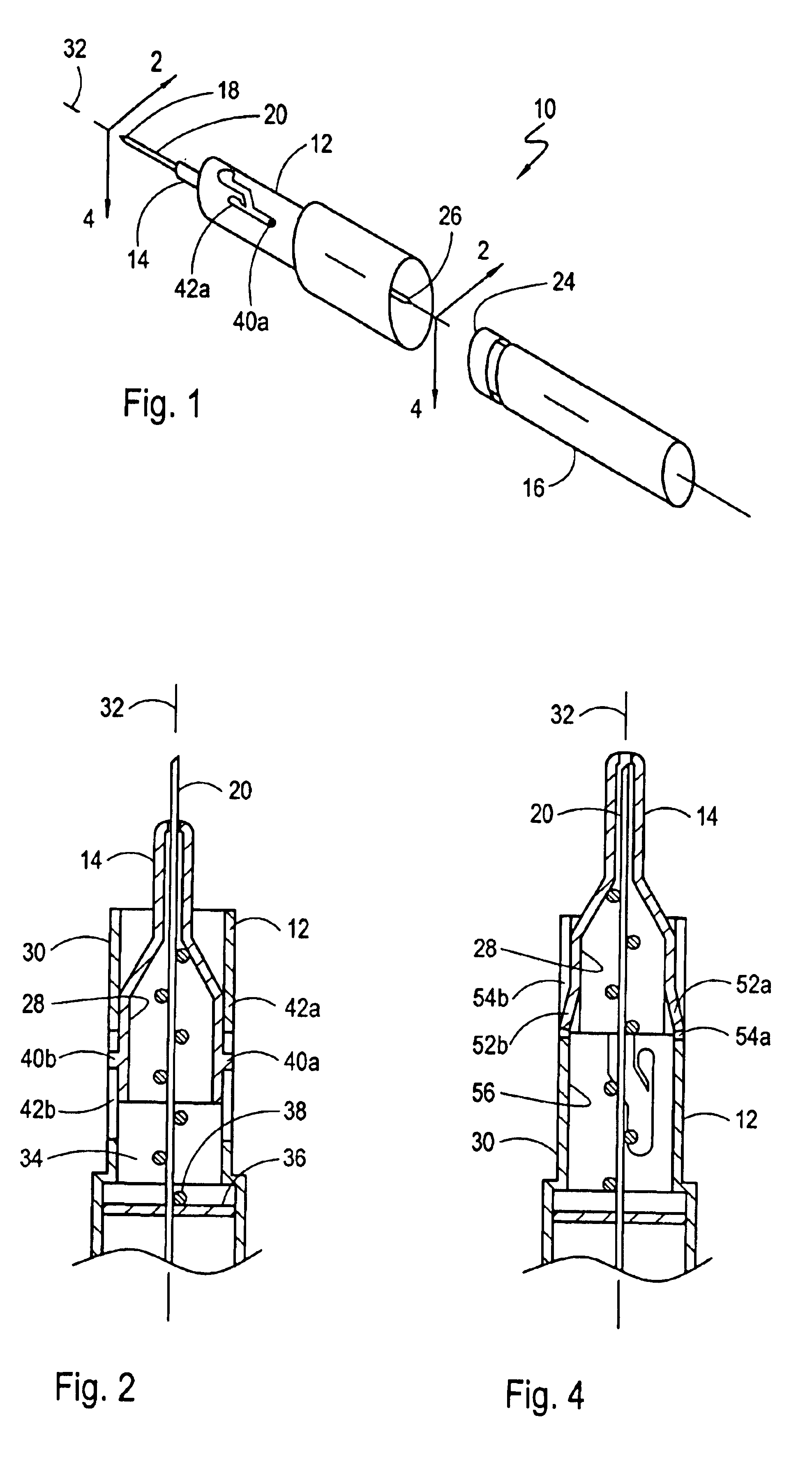
[0009]In greater structural detail, the needle guard and base member components of the device are each formed with a cylindrical shaped portion sized to allow the cylindrical portion of one component to slide over the cylindrical shaped portion of the other component. With this cooperation of structure, the cylindrical portions can be coaxially positioned on a single axis to allow for the reciprocal axial movement of the needle guard relative to the base member. Also, an aperture extends through the needle guard / base member assembly that is sized to allow the needle of the syringe to pass through the aperture. This cooperation of structure allows the spring to be seated between the needle guard and the base member to urge the needle guard and base member in opposite axial directions.
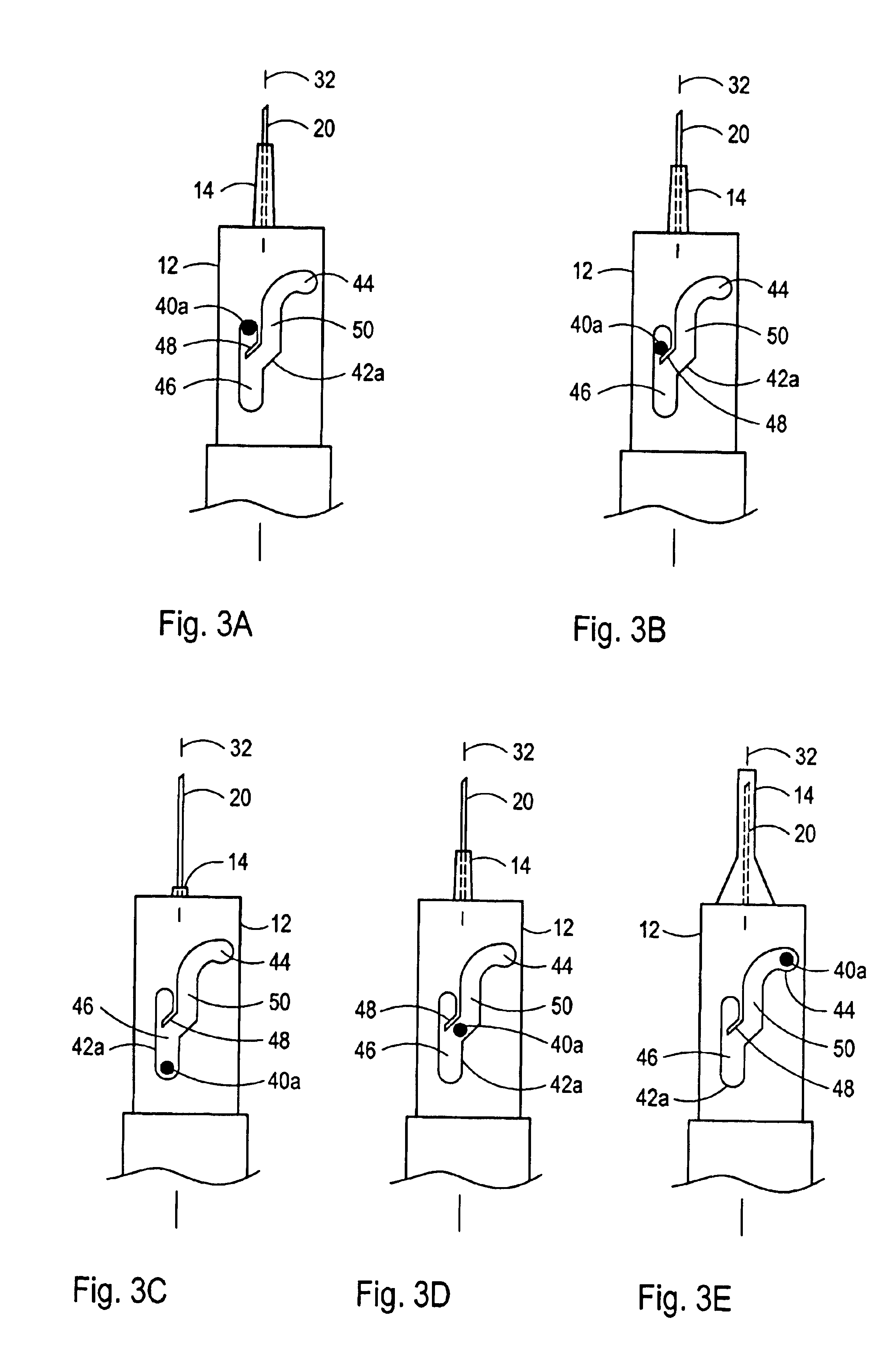
[0013]With the needle inserted into the patient at a desired penetration depth, the syringe can be used to inject or withdraw fluid from the patient. Next, the needle is removed from the patient. During the initial withdrawal of the needle from the patient, the needle guard remains in contact with the patient while the syringe and base member are pulled away from the patient. Specifically, the spring expands to hold the needle guard against the patient during initial withdrawal. In addition, the movement of the base member relative to the needle guard during needle removal causes the plug to translate along the linear track from the second position and towards the arm. At the arm, the plug is directed from the linear track and to the locking cutout that is located at a position to ensure that the needle guard covers the needle when the plug is in the locking cutout. As indicated above, an interaction between a slot and tab prevents the plug from rotating out of the locking cutout. Thus, once the plug is in the locking cutout, the needle guard becomes locked over the needle to protect against accidental needle sticks or inadvertent re-use.

Problems solved by technology

For example, a sudden movement by a patient can cause a health care worker to lose control of a syringe, resulting in injury.
Additionally, injuries often result when contaminated, unprotected needles are left unattended or are disposed of improperly.
Moreover, attempts to manually recap a needle after filling the syringe with a medicament or attempts to recap a syringe needle following a syringe procedure can also result in injury.
In addition to accidental needle sticks, unnecessary exposure to bloodborne pathogens can result when a health care worker mistakenly re-uses a contaminated needle on a patient.
Unfortunately, accidental needle sticks have the potential to expose a health care worker to a life-threatening virus such as hepatitis or HIV.
It is to be appreciated that the costs associated with the testing, lab work, the workers lost time, and the associated tracking and administrative costs, can be considerable.
Generally, this restraint prevents the relatively smooth action required to accurately insert the needle into a target location such as a vein.
In some cases, the inability of the needle guard to rotate smoothly can prevent the needle guard from properly retracting.
When this happens, the needle cannot be inserted to the proper penetration depth and the result is often an unsuccessful syringe procedure.

Method used


Image

  • Position guide for a needle guard
  • Position guide for a needle guard
  • Position guide for a needle guard

Examples


Embodiment Construction

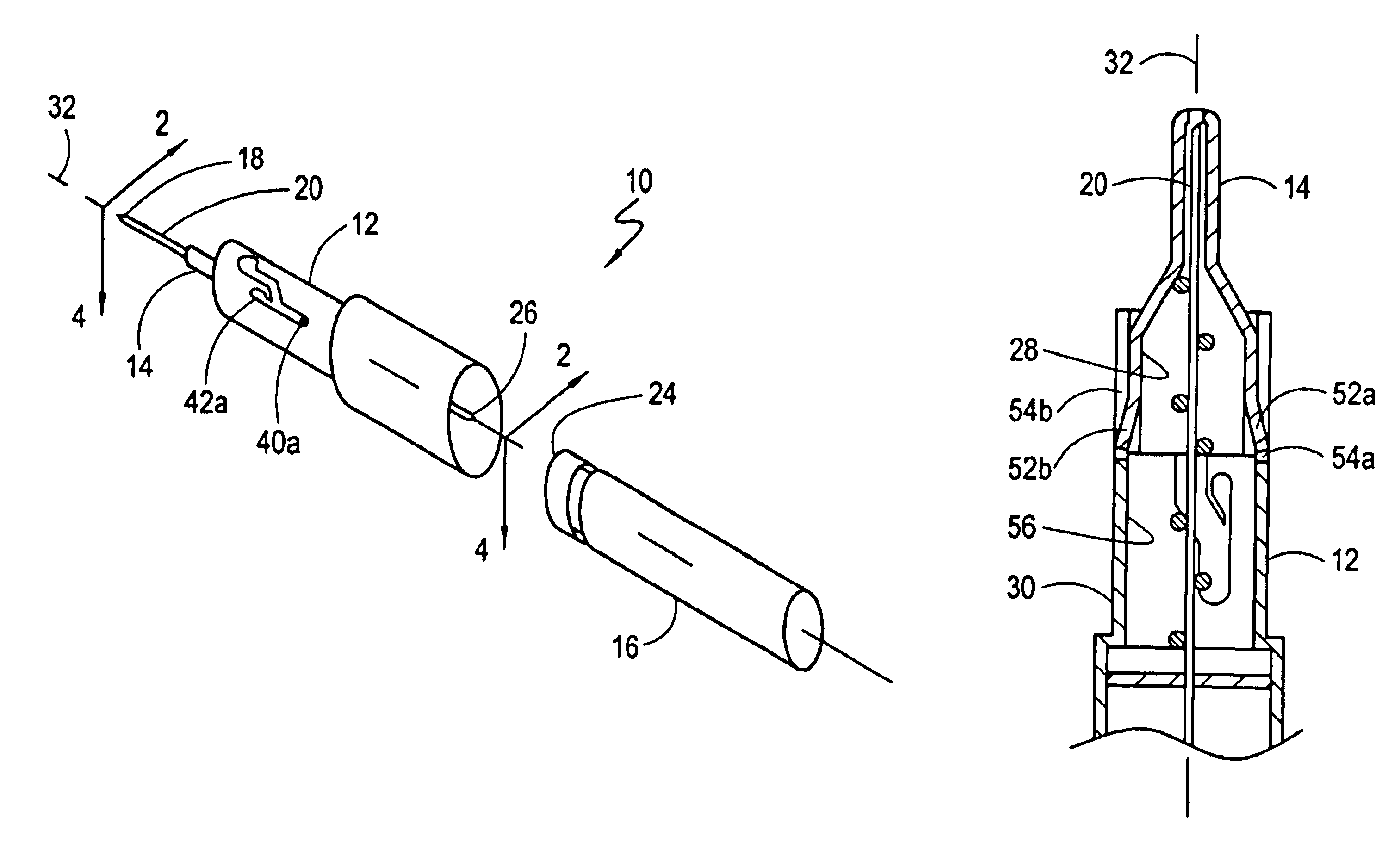
[0025]Referring initially to FIG. 1, a blood collection system is shown and generally designated 10. As shown, the system 10 includes a base member 12 and a needle guard 14. Functionally, the system 10 can be used to safely draw blood from a patient and into the blood collection vial 16. Specifically, the distal tip 18 of the hollow needle 20 can be used to pierce a patient's vein causing blood to flow into the hollow needle 20. As further shown, a septum 24 can be placed over the opening of the blood collection vial 16 allowing the septum 24 to be pierced by the proximal tip 26 of the needle 20 to establish fluid communication between the blood collection vial 16 and the needle 20.

[0026]In functional overview, the interaction between the base member 12 and the needle guard 14 causes the needle guard 14 to retract over the needle 20 during insertion of the needle 20 into a patient. After the needle 20 has been withdrawn from the patient, the needle guard 14 passively re-covers and i...


PUM


Abstract

A device for covering and protecting a syringe needle after a syringe procedure includes a needle guard component, a base member component and a spring. The needle guard and base member components of the device are both formed with cylindrical shaped portions that are arranged coaxially. The base member is affixable to the syringe with the spring positioned between the needle guard and base member components to urge the components in opposite axial directions. One component is formed with a plug that extends into a guide mechanism formed on the other component. The guide mechanism includes a locking cutout, an axially aligned linear track and a deflectable arm. The arm deflects to allow linear plug movement during retraction of the needle guard over the needle and redirects the plug to the locking cutout when the needle guard moves to re-cover the needle.

Description

FIELD OF THE INVENTION[0001]The present invention pertains generally to syringes for medical use. More particularly, the present invention pertains to passive safety devices for medical syringes. The present invention is particularly, but not exclusively, useful for passively covering and protecting the needle of a medical syringe at the completion of a syringe procedure.BACKGROUND OF THE INVENTION[0002]Accidental needle sticks can occur in several ways. For example, a sudden movement by a patient can cause a health care worker to lose control of a syringe, resulting in injury. Additionally, injuries often result when contaminated, unprotected needles are left unattended or are disposed of improperly. Moreover, attempts to manually recap a needle after filling the syringe with a medicament or attempts to recap a syringe needle following a syringe procedure can also result in injury. In addition to accidental needle sticks, unnecessary exposure to bloodborne pathogens can result when...

Claims


Application Information

Patent Timeline
Patent Type & Authority Patents(United States)
IPC IPC(8): A61M5/32
CPCA61M5/3272A61M5/3257A61M2005/3267
Inventor ASBAGHI, HOOMAN A.
Owner INVIRO MEDICAL DEVICES LTD
Learn More