Vacuum-insulated exhaust treatment devices with radially-extending support structures

a technology of exhaust treatment device and support structure, which is applied in the direction of machines/engines, mechanical equipment, separation processes, etc., can solve the problems of large amount of tailpipe hydrocarbon emissions, low efficiency of catalytic converters, and low concentration of exhaust hydrocarbons, so as to reduce undesirable emissions

Inactive Publication Date: 2005-04-26
BENTELER AUTOMOTIVE CORP
View PDF8 Cites 26 Cited by
  • Summary
  • Abstract
  • Description
  • Claims
  • Application Information

AI Technical Summary

Benefits of technology

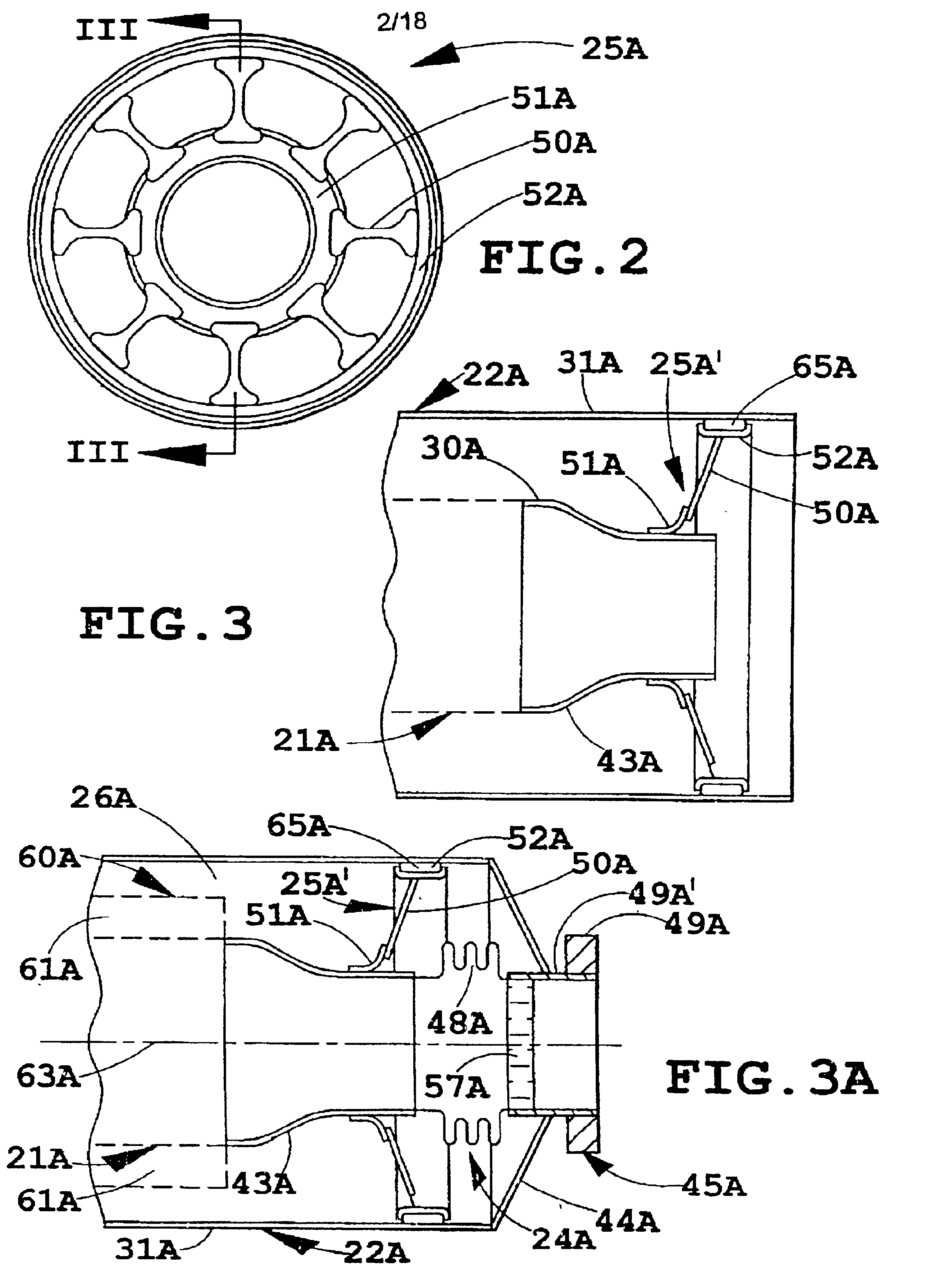
[0008]In one aspect of the present invention, an exhaust treatment device for vehicles includes an inner housing having an inlet and an outlet defining a longitudinal direction and having a thermally-activated exhaust treatment device therein chosen to reduce undesirable emissions from the exhaust of a combustion engine as the exhaust passes from the inlet to the outlet. An outer housing encloses the inner housing but characteristically does not contact the inner housing. The outer housing includes an inlet and an outlet that align with the inlet and outlet of the inner housing, and further the inner and outer housing include walls forming a sealed cavity around the inner housing. The cavity has a vacuum drawn therein. Supports comprising a plurality of spokes are provided that extend radially between the inner and outer housings.
[0010]In another aspect of the present invention, an exhaust treatment device for vehicles includes an inner housing having an inlet and an outlet defining a longitudinal direction and having a thermally-activated exhaust treatment device therein chosen to reduce undesirable emissions from the exhaust of a combustion engine as the exhaust passes from the inlet to the outlet. An outer housing encloses the inner housing but characteristically does not contact the inner housing. The outer housing including an inlet and an outlet that align with the inlet and outlet of the inner housing, the inner and outer housing including walls forming a sealed cavity around the inner housing, the cavity having a vacuum drawn therein. Supports are provided that support the inner housing in the outer housing. The supports include a radially-extending body and including a foot that slidably engages at least one of the inner and outer housing.

Problems solved by technology

A problem exists in that a large part of tailpipe hydrocarbon emissions occur during the initial cold start phase when the catalytic converter is least effective.
Specifically, cold internal combustion engines produce an exhaust having a relatively high concentration of emissions, while “cold” catalytic converters are least able to deal with the emissions because their catalysts are not efficient until they heat up and reach an operating temperature.
However, unacceptable amounts of heat loss by radiation and conduction may still occur at locations where an inner housing is supported inside an outer housing of a catalytic converter.
Further, it is not easy to consistently and securely support an inner housing within an outer housing without allowing any direct physical contact between the two housings, especially on a production basis.
This is because production processes and the manufactured components exhibit variations and have tolerances that make it difficult to maintain a precise and consistent gap between inner and outer housings on all assemblies produced.
Further, where a relatively high vacuum is drawn in the space between the inner and outer housings, the problem of maintaining the gap is made significantly more difficult.
This is because the existence of the vacuum creates unbalanced forces on the housing sidewalls, and tends to draw and deform the sidewalls of the inner and outer housings toward each other.
Further, even if a gap is successfully made that extends completely around the inner housing between the inner and outer housings, differences in thermal expansion can cause contact between the inner and outer housings.
Another problem is the abuse that occurs to the catalytic converter when in service under the vehicle, including impacts and shocks from stones and debris and temperature spikes from high speed / load events or engine misfires.
On the other hand, any supports that are provided for holding the inner housing in non-contact with the outer housing cannot be so massive and large as to create a thermally conductive path that defeats the effectiveness of the other insulating features.
Thus, designing a support system that supports the inner housing in the outer housing in a reliable and stable manner and that at all times prevents contact, yet that does not itself provide unwanted conduction, is not an insignificant or easily solved problem.
This reliably maintains spacing between the inner and outer tubes, but is not satisfactory since it can result in significant heat transfer along the fibers from the inner tubes to the outer tubes.
Further, unless there are many fibers or larger fibers with strength, the fibers will crush and not provide a satisfactory insulating value while in service.
Still further, fibrous insulation is not inexpensive.
Particulate traps are least effective at cold starts which is when the problem of carbon particulate emissions and creation of soot is the greatest in diesel engines.

Method used


Image

  • Vacuum-insulated exhaust treatment devices with radially-extending support structures
  • Vacuum-insulated exhaust treatment devices with radially-extending support structures
  • Vacuum-insulated exhaust treatment devices with radially-extending support structures

Examples


Embodiment Construction

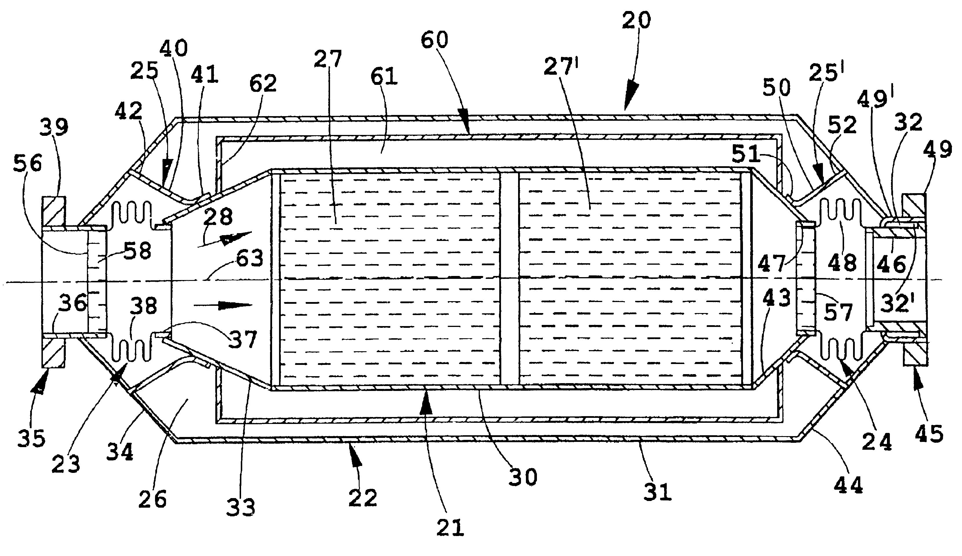
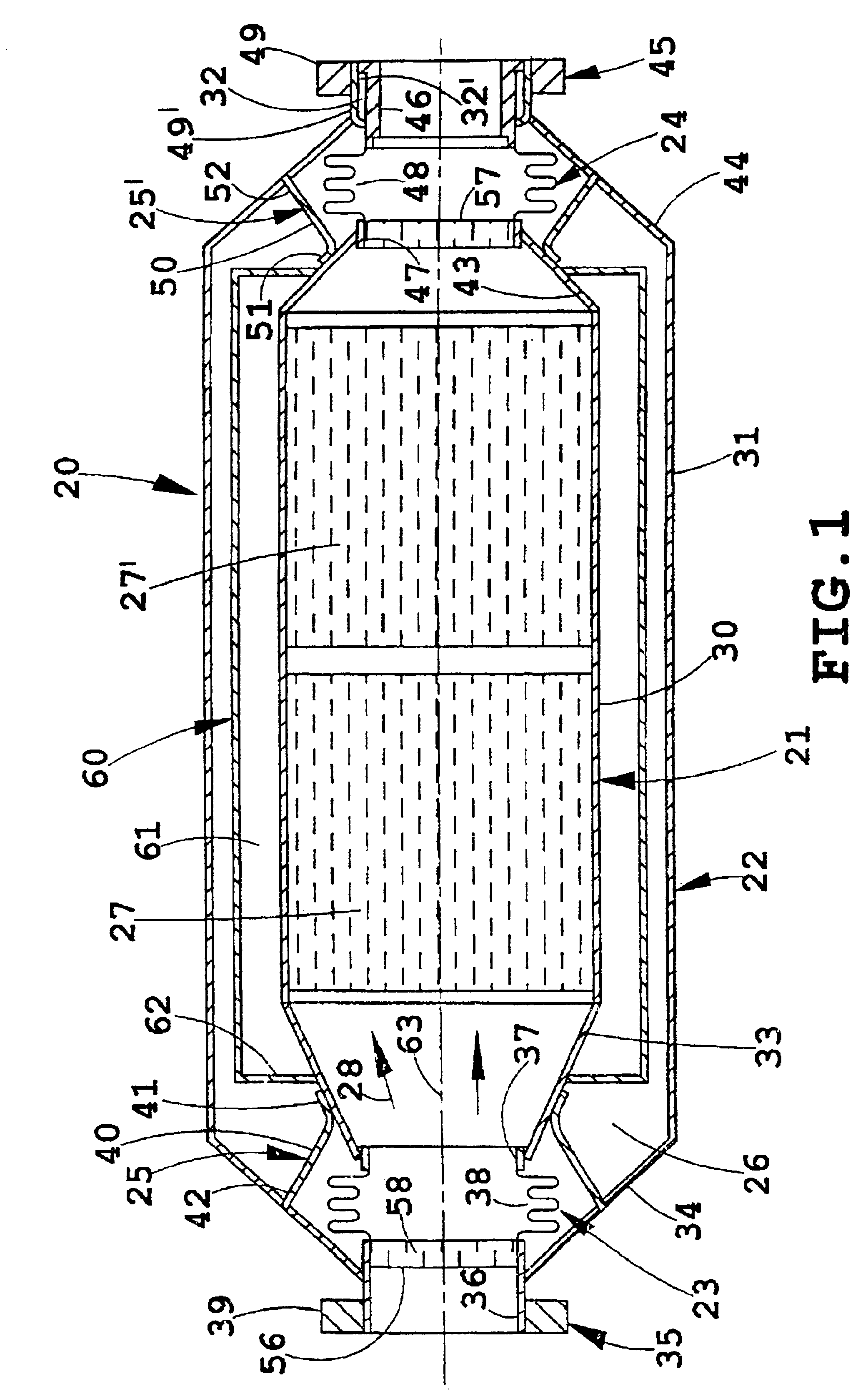
[0071]The illustrated catalytic converter 20 (FIG. 1) is a vacuum-insulated converter having a core or inner housing 21 positioned within and insulated from a jacket or outer housing 22. Expansion joints 23 and 24 are provided at each end of the inner housing 21, and supports 25 and 25′ are provided to support the inner housing 21 within the outer housing 22 while maintaining a vacuum-insulating cavity 26 forming a relatively constant gap around the inner housing 21. A sufficient vacuum is drawn on the cavity 26 so as to eliminate heat loss from air conduction and convection. The supports 25 and 25′ within the converter design are particularly configured to accommodate longitudinal thermal expansion of the hot inner housing 23 relative to the cool outer housing 24. The internal supports 25 and 25′ bridge the vacuum insulation and are sufficiently stiff to accommodate dynamic (vibration and impact) loads at temperature, yet are flexible enough to accommodate unequal thermal expansion...


PUM

PropertyMeasurementUnit
angleaaaaaaaaaa
thickaaaaaaaaaa
angleaaaaaaaaaa

Abstract

An exhaust treatment device, such as a catalytic converter assembly (20) for vehicles includes an inner housing (21) having an inlet and an outlet defining a longitudinal direction (63) and having a catalytic material (27, 27′) therein chosen to reduce undesirable emissions from the exhaust of a combustion engine as the exhaust passes from the inlet to the outlet. The catalytic converter assembly (20) further includes an outer housing (22) enclosing the inner housing (21) but characteristically not contacting the inner housing (21), the outer housing (22) including an inlet and an outlet that align with the inlet and outlet of the inner housing (21), the inner and outer housing (21, 22) including walls (30, 31) forming a sealed cavity (26) around the inner housing (21), the cavity (26) having a vacuum drawn therein. The catalytic converter assembly (20) further includes supports (25) of various configurations and materials that extend radially between the inner and outer housings (21, 22).

Description

[0001]This application claims benefit of 60 / 116,828 filed Jan. 22, 1999.BACKGROUND OF THE INVENTION[0002]The present apparatus relates to automotive exhaust systems, and more particularly relates to thermally-activated exhaust treatment devices that are vacuum-insulated and that have expansion joints and supports within the devices designed to accommodate differences in thermal expansion of a “hot” inner housing relative to a “cool” outer housing.[0003]Most vehicle exhaust systems and particularly exhaust systems of vehicles powered by internal combustion engines are equipped with catalytic converters for reducing noxious emissions in exhaust gases. A problem exists in that a large part of tailpipe hydrocarbon emissions occur during the initial cold start phase when the catalytic converter is least effective. Specifically, cold internal combustion engines produce an exhaust having a relatively high concentration of emissions, while “cold” catalytic converters are least able to deal ...

Claims


Application Information

Patent Timeline
Patent Type & Authority Patents(United States)
IPC IPC(8): F01N7/14F01N7/18B01D53/94F01N13/14F01N13/18
CPCB01D53/9454F01N13/14Y02T10/22F01N2470/12F01N2470/24F01N13/1816Y02A50/20Y02T10/12
Inventor BIEL, JR., JOHN P.HILL, JR., FREDERICK B.MEWS, LANCERIGSBY, DONALD R.
Owner BENTELER AUTOMOTIVE CORP
Why Eureka
Try Eureka