
Operating method for a particle filter

a particle filter and filter technology, applied in the direction of machines/engines, mechanical equipment, separation processes, etc., can solve the problems of degrading the filter and engine, increasing the impermeability of the filter, and limiting the continuous operation of the particle filter, so as to reduce undesirable emissions, increase the impermeability of the filter, and restore the filter permeability

Active Publication Date: 2013-09-19
FORD GLOBAL TECH LLC
View PDF23 Cites 0 Cited by
  • Summary
  • Abstract
  • Description
  • Claims
  • Application Information

AI Technical Summary

Benefits of technology

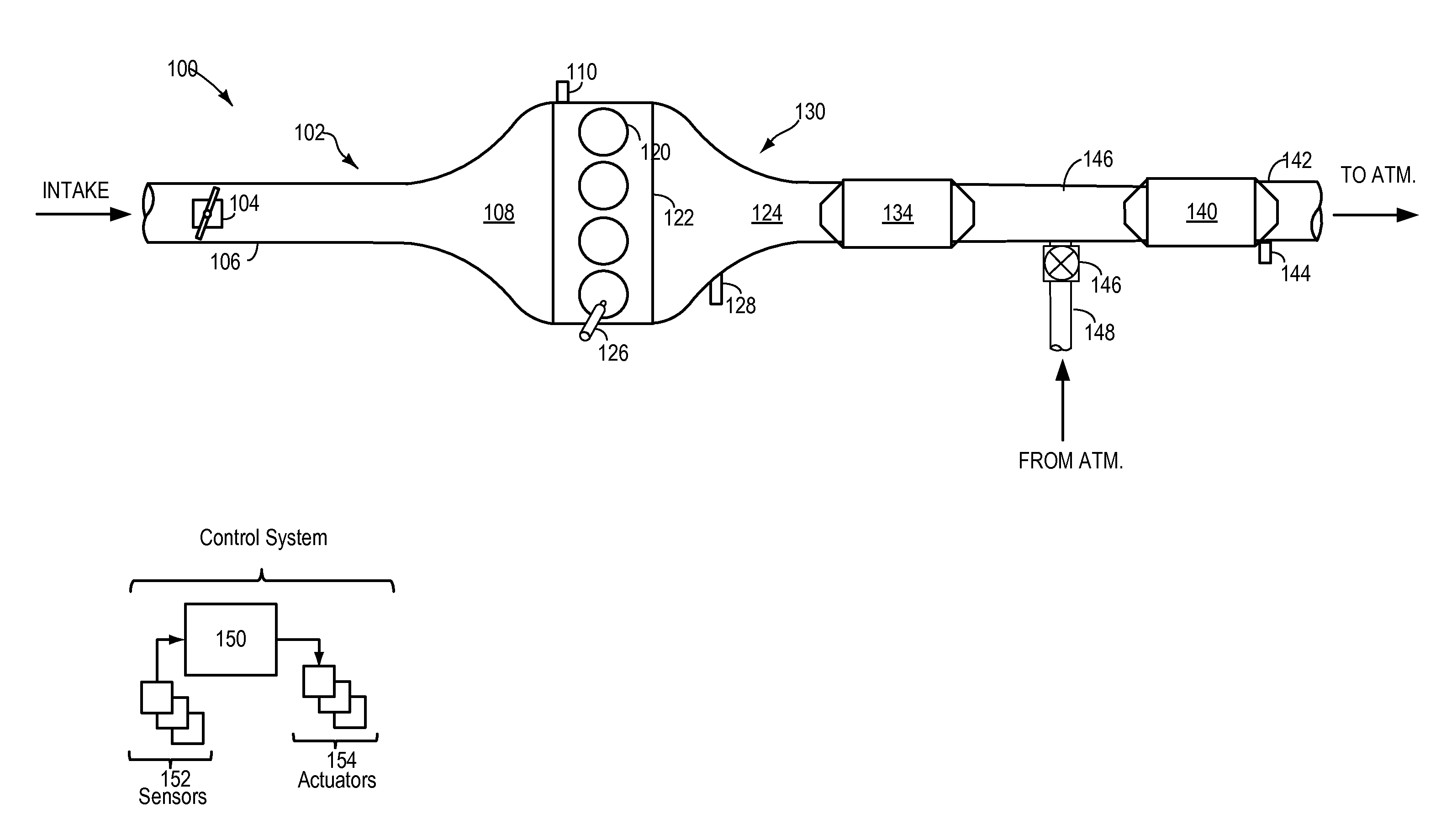
The patent text describes a system and method for controlling the operation of a particle filter in an exhaust-gas path of an internal combustion engine. The system includes a sensor to measure the mass airflow rate and temperature of the exhaust gas. By controlling the rate at which ambient air enters the filter, the system can prevent uncontrolled regeneration (also known as spontaneous combustion) of the filter, which can degrade the filter and engine. The system also includes a method for regenerating the filter at a controlled rate, which helps to maintain its efficiency and reduce emissions. The technical effects of the patent text include improved control of particle filter operation and reduced emissions from internal combustion engines.

Problems solved by technology

The continuous operation of a particle filter may be limited by its absorption capacity.
Further, extended use of a particle filter may contribute to counter-pressure within the exhaust system resulting from an increasing impermeability of the filter as the amount of solid particle content increases.
If the regeneration is not performed regularly in order to limit the amount of deposited solid material, a spontaneous combustion may occur, which may degrade the filter and engine.
During the combustion process, temperatures of over 600 degrees Celsius may be reached, which may degrade the substrate of the particle filter.
The risk of damage is particularly high if the combustion process takes place in an uncontrolled manner that may be initiated, for example, by an unexpectedly high amount of deposited solid material.
However, regular controlled regeneration cycles increase the fuel consumption.
Further, regeneration may not be possible in all operating conditions.

Method used


Image

  • Operating method for a particle filter
  • Operating method for a particle filter
  • Operating method for a particle filter

Examples


Embodiment Construction

[0013]Exhaust gas after-treatment devices (EG-ATDs) may be embodied as wall-flow particle filters. Wall flow particle filters work to remove solid material present within the exhaust gas, such as soot, and store the removed particles in the substrate wall of the filter. The volume of wall-flow filters is limited so that, after a period of operation, the filter may become full and may lose its capacity to continue to store removed particles from exhaust gas, lowering filter efficiency. Filter regeneration may allow the filter to return to its original operating capacity for continued operation.

[0014]Controlled regeneration may be defined as regeneration initiated by the control system and may include increasing the heat within the filter to the point of combustion thus burning of the trapped particles. Combustion may be initiated by introducing a fuel rich mixture into the exhaust system so that still-unburned fuel within the exhaust gas may combust in the filter. Regeneration may al...


PUM

PropertyMeasurementUnit
temperaturesaaaaaaaaaa
mass flow rateaaaaaaaaaa
temperatureaaaaaaaaaa

Abstract

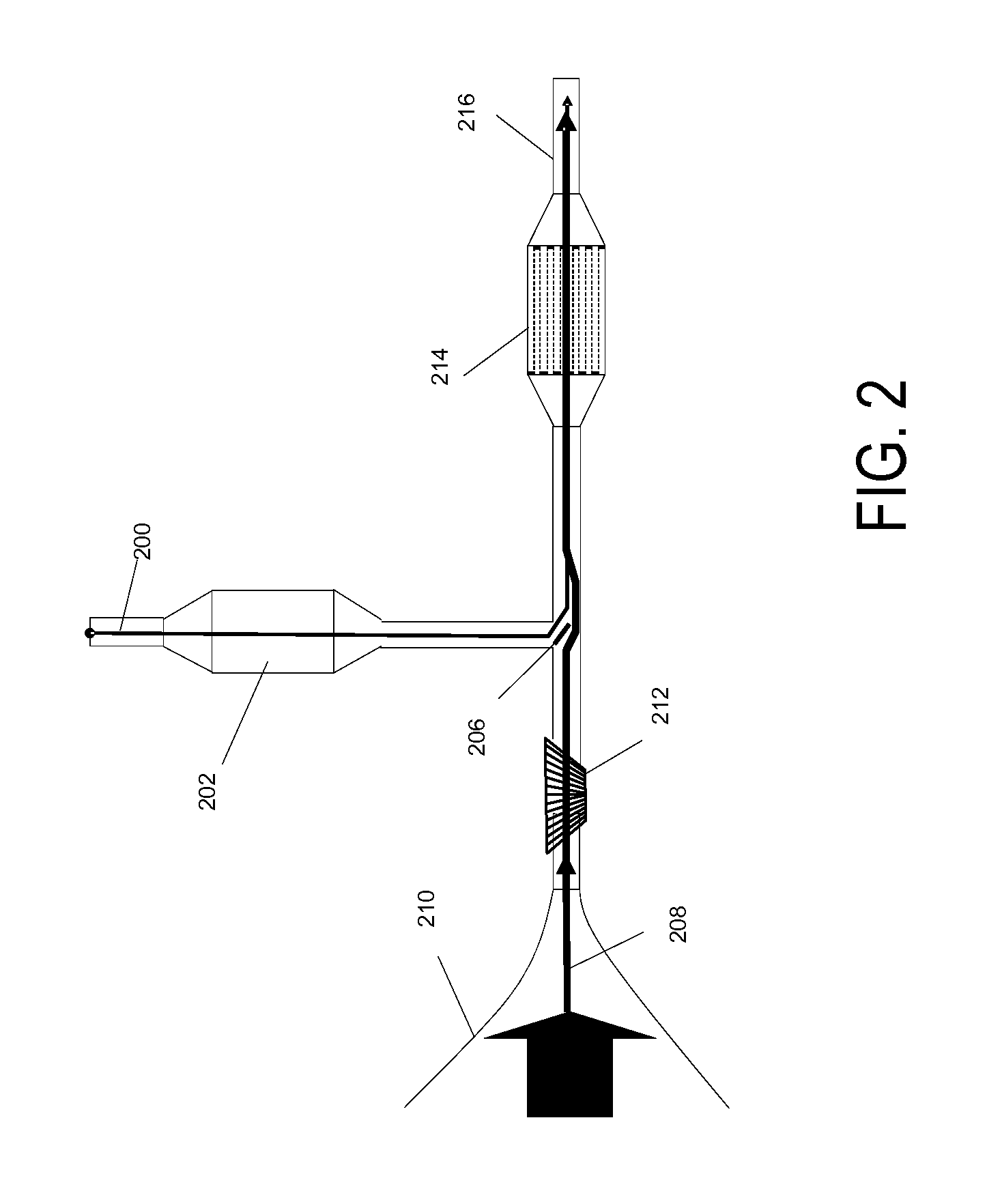
The systems and methods herein relate the operation of a particle filter which is arranged in an exhaust-gas path of an internal combustion engine, to a device for exhaust-gas aftertreatment which can be operated in accordance with the method that comprises determining a mass flow rate of an exhaust-gas flow flowing in the exhaust-gas path; and supplying ambient air into the exhaust-gas path as a function of the determined mass flow rate. By this method, the spontaneous regeneration of a particle filter within the exhaust system may be abated.

Description

CROSS REFERENCE TO RELATED APPLICATIONS[0001]The present application claims priority to German Patent Application 102012204099.4, filed on Mar. 15, 2012, the entire contents of which are hereby incorporated by reference for all purposes.BACKGROUND AND SUMMARY[0002]The systems and methods herein relate to the operation of a particle filter, within an exhaust-gas path of an internal combustion engine that is coupled to an exhaust-gas aftertreatment device which may be operated in accordance with a method of operation of a motor vehicle.[0003]In wall-flow particle filters, such as soot filters in internal combustion engines, solid material is filtered out of exhaust gas stored on the wall of the substrate of the particle filter. Particles removed by a properly functioning filter from exhaust gas reduce undesirable emissions to meet emissions and operation standards.[0004]The continuous operation of a particle filter may be limited by its absorption capacity. A process called regenerati...

Claims


Application Information

Patent Timeline
Patent Type & Authority Applications(United States)
IPC IPC(8): F02M35/08
CPCF02M35/08F01N9/002F01N2900/1411Y02T10/47F01N3/023F01N2260/08F01N2270/00F01N3/30Y02T10/40
Inventor YACOUB, YASSER MOHAMED SAYED
Owner FORD GLOBAL TECH LLC
Learn More