Vacuum-insulated exhaust treatment device with phase change materials and thermal management system

a phase change material and exhaust treatment technology, applied in the direction of machines/engines, separation processes, lighting and heating apparatus, etc., can solve the problems of large hydrocarbon emissions of tailpipes, untreated exhaust gases, and inability to efficiently react with the reaction, etc., to achieve the effect of reducing undesirable emissions

Inactive Publication Date: 2005-04-05
BENTELER AUTOMOTIVE CORP
View PDF8 Cites 49 Cited by
  • Summary
  • Abstract
  • Description
  • Claims
  • Application Information

AI Technical Summary

Benefits of technology

In one aspect of the present invention, a thermally-activated exhaust treatment device is provided, such as a catalytic converter adapted to control exhaust emissions in a vehicle. The exhaust treatment device includes an inner housing having a first inlet and a first outlet defining a longitudinal direction and having an exhaust treatment device therein chosen to reduce undesirable emissions from exhaust of a combustion engine as the exhaust passes from the first inlet to the first outlet. The device further includes an outer housing enclosing the inner housing but characteristically not contacting the inner housing. The outer housing includes a second inlet and a second outlet that aligns with the first inlet and the first outlet of the inner housing. The inner and outer housings includes walls forming a sealed insulation cavity around the inner housing, with the insulation cavity having a vacuum drawn therein. An intermediate housing is positioned adjacent to the inner housing that includes metal phase change material.
In another aspect of the present invention, a thermally-activated exhaust treatment device is provided, such as a catalytic converter adapted to control exhaust emissions from a diesel engine. The device includes an inner housing having a first inlet and a first outlet defining a longitudinal direction and having an exhaust treatment device therein chosen to reduce undesirable emissions in exhaust of a diesel engine as the exhaust passes from the first inlet to the first outlet. The device further includes an outer housing enclosing the inner housing but characteristically not contacting the inner housing. The outer housing includes a second inlet and a second outlet that aligns with the first inlet an the first outlet of the inner housing. The inner and outer housings include walls forming a sealed insulation cavity around the inner housing, with the insulation cavity having a vacuum drawn therein. A thermal management system is operably connected to the insulation cavity that is constructed to control heat flow from the inner housing to maximize the time the catalytic material is within a predetermined optimum temperature operating range that includes an upper limit and a lower limit.

Problems solved by technology

A problem exists in that a large part of tailpipe hydrocarbon emissions occur during the initial cold start phase when the catalytic converter is least effective.
Until the converter is heated to a sufficiently high temperature, these reactions do not occur efficiently and exhaust gases pass through the system untreated.
However, passive thermal energy storage systems have problems.
This will require some additional time during which untreated exhaust gases will be emitted.
Thus, while the above-discussed design is effective in reducing “cold start” emissions when it is hot, it actually exacerbates the “cold start” problem whenever the converter has been allowed to cool.
Notably, no matter how effectively the converter stores heat, there will be times when it has cooled and will suffer from some degree of “cold start” emissions.
There are some fundamental problems in using a salt PCM.
One problem is that the thermal conductivity of a salt is relatively low, resulting in extended vehicle driving times to fully melt the PCM and realize the full heat storage of the PCM.
Another problem is the large thermal expansion of most salts from ambient temperature to elevated temperatures typical of an auto exhaust.
This expansion can be as high as 30% which results in inefficient packaging since allowance must be made in the PCM container for this expansion.
This is undesirable since the area under a vehicle is very confined and at a premium, particularly as vehicles are built to ride closer and closer to the road surface.
However, the electrically heated and controlled hydrogen source disclosed in Benson U.S. Pat. No. 5,477,676 to prevent the converter from overheating requires complex and expensive wiring to the catalytic converter.
This wiring and control system also adds to the vulnerability of the exhaust system to failure and increases the risk of a warranty liability or expensive model recall action by the manufacturer.
This can be a serious problem, particularly given the severe environments that exhaust systems are subjected to.
Particulate traps are least effective at cold starts, which is when the problem of carbon particulate emissions and creation of soot is the greatest in diesel engines.

Method used


Image

  • Vacuum-insulated exhaust treatment device with phase change materials and thermal management system
  • Vacuum-insulated exhaust treatment device with phase change materials and thermal management system
  • Vacuum-insulated exhaust treatment device with phase change materials and thermal management system

Examples


Embodiment Construction

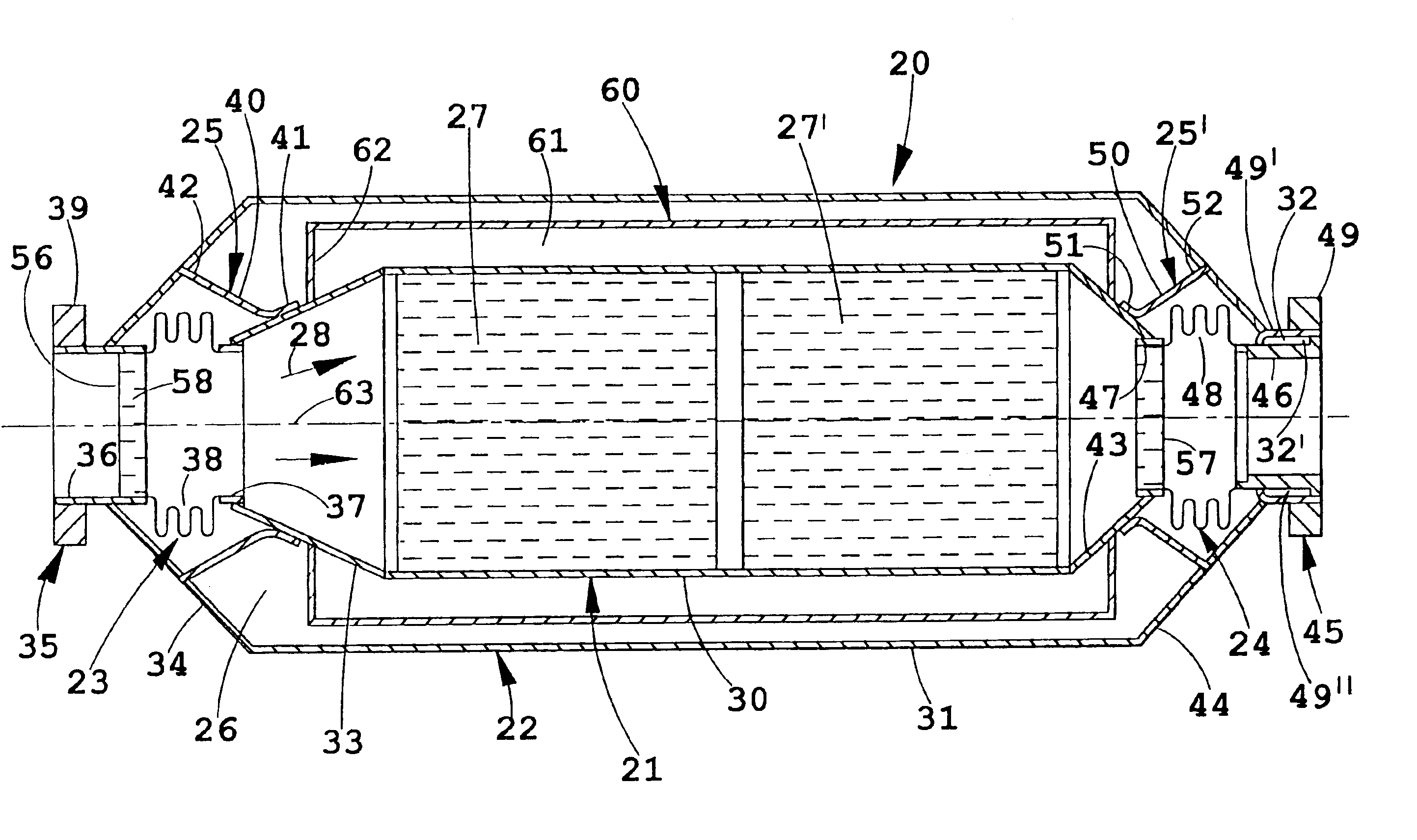
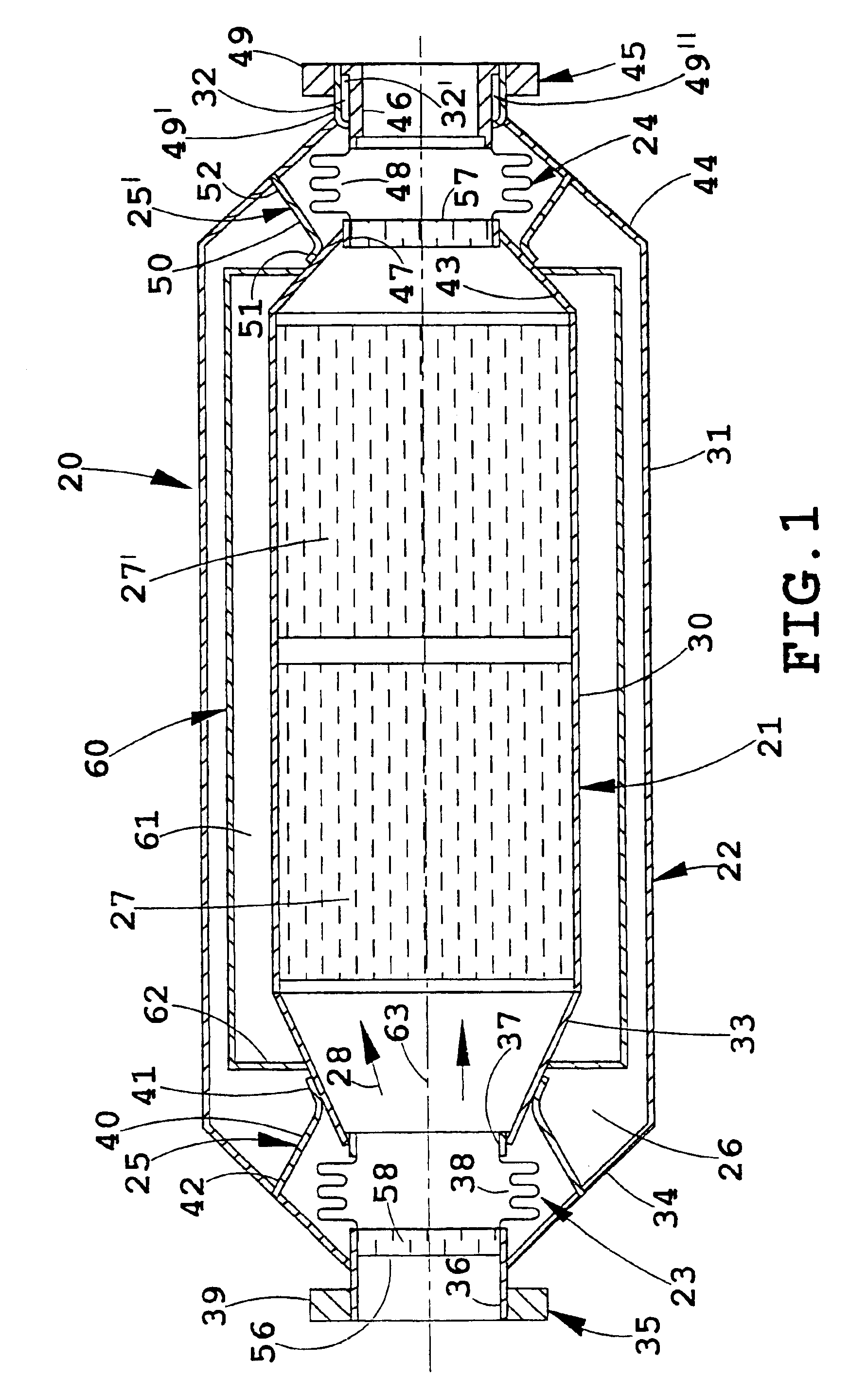
The illustrated catalytic converter 20 (FIG. 1) is a vacuum-insulated converter having an inner housing 21 positioned within and insulated from an outer housing 22. Expansion joints 23 and 24 are provided at each end of the inner housing 21, and supports 25 and 25′ are provided to support the inner housing 21 within the outer housing 22 while maintaining a cavity 26 forming a relatively constant gap around the inner housing 21. A sufficient vacuum is drawn on the cavity 26 so as to minimize heat loss from air conduction and convection. The supports 25 and 25′ within the converter design are particularly configured to accommodate longitudinal thermal expansion of the hot inner housing 21 relative to the cool outer housing 22. The internal supports 25 and 25′ bridge the vacuum insulation and are sufficiently stiff to accommodate dynamic (vibration and impact) loads at temperature, yet are flexible enough to accommodate unequal thermal expansion of the inner and outer housings 21 and 2...


PUM

PropertyMeasurementUnit
eutectic temperatureaaaaaaaaaa
temperatureaaaaaaaaaa

Abstract

A thermally-activated exhaust treatment device, such as a catalytic converter (20) adapted to control exhaust emissions in a vehicle, includes a core having an inner housing (21) and a catalytic material (27) chosen to reduce undesirable emissions from the exhaust of a combustion engine. A jacket includes an outer housing (22) enclosing the inner housing (21) but characteristically not contacting the inner housing (21). The inner and outer housings (21, 22) include walls (30, 31) forming a vacuum-drawn sealed insulation cavity (26) around the inner housing (21). A chamber (60) positioned adjacent the inner housing (21) includes low melting point metal phase change material (61). A thermal management system is operably connected to the insulation cavity (26) that is constructed to control heat flow from the inner housing (21) to maximize the time the catalytic material (27) is within a predetermined optimum temperature operating range or limit catalyst maximum temperature.

Description

BACKGROUND OF THE INVENTIONThe present apparatus relates to automotive exhaust systems, and more particularly relates to catalytic converters and particulate traps that are vacuum insulated and that have phase change materials to assist in retention of heat and further that are adapted to treat emissions, such as are found in gasoline engine exhaust and diesel engine exhaust.Most vehicle exhaust systems and particularly exhaust systems of vehicles powered by internal combustion engines are equipped with engine exhaust treatment systems for reducing noxious emissions in exhaust gases. Engine exhaust treatment systems consist primarily of a catalytic converter which converts toxic exhaust emissions to non-toxic gases. The oxidative and reductive reactions that convert the emissions occur on the hot catalytically active surface of the converter. A problem exists in that a large part of tailpipe hydrocarbon emissions occur during the initial cold start phase when the catalytic converter...

Claims


Application Information

Patent Timeline
Patent Type & Authority Patents(United States)
IPC IPC(8): B01D53/88B01D53/94
CPCB01D53/885B01D53/94F28D20/02
Inventor BIEL, JR., JOHN PETERHILL, JR., FREDERICK B.BURCH, STEVEN D.PENNEY, TERRY R.
Owner BENTELER AUTOMOTIVE CORP
Why Eureka
Try Eureka