Method and a device for reducing hysteresis or imprinting in a movable micro-element

a micro-element and hysteresis reduction technology, applied in the field of movable micro-elements, can solve the problems of reducing the accuracy of mirror deflection, virtually impossible to predict and compensate the required address voltage, and it is impossible, or at least very difficult, to use a collectively addressable pixel counter electrode as a balance. to achieve the effect of reducing the imprinting

Inactive Publication Date: 2005-04-26
MICRONIC LASER SYST AB +1
View PDF17 Cites 257 Cited by
  • Summary
  • Abstract
  • Description
  • Claims
  • Application Information

AI Technical Summary

Benefits of technology

[0005]In view of the foregoing background, in the movable micro-elements and in the method for addressing individual movable micro-elements, such as for example mirror elements in a SLM, it is critical to reduce the imprinting effect.
[0006]Accordingly, it is an object of the present invention to provide an improved movable micro-element, which overcomes or at least reduces the above-mentioned problem.
[0010]In another embodiment of the invention said predetermined pulsed signal is capable to clear out a potential difference between said address electrode and said movable micro-element and thereby restoring said movable micro-element to said electrostatically unattracted state.
[0025]In still another embodiment of the invention said predetermined pulsed signal is capable to clear out a potential difference between said address electrode and said counter electrode and thereby restoring said movable micro-element to said non addressed state.
[0026]In still another embodiment of the invention said predetermined pulsed signal is capable to clear out a potential difference between said address electrode and said counter electrode and thereby restoring said movable micro-element to an electrostatically unattracted state.
[0036]The invention relates also to a method of reducing an imprinting effect of a movable micro-element arranged spaced apart from a surface, where said surface comprises at least one electrode.

Problems solved by technology

Hysteresis or imprinting of mirror deflection amplitude in Spatial Light Modulators (SLM), which leads to a shift in a required address voltage for a preferred mirror deflection, is a problem since it reduces the accuracy of the mirror deflection.
The time constants for these phenomena are in the region of minutes / hours making it virtually impossible to predict and compensate the required address voltages for an arbitrary pattern in a mask writer or a direct writer using a state of the art SLM technology.
A problem with a compensation for the imprinting is that the mirrors in the SLM are loaded with data row by row, always from the same direction.
It is therefore also impossible, or at least very difficult, to use a collectively addressable pixel counter electrode as a balance for the imprinting effect unless the SLM is redesigned to load the data from the first and the last row every second time to average the duty-cycles.

Method used


Image

  • Method and a device for reducing hysteresis or imprinting in a movable micro-element
  • Method and a device for reducing hysteresis or imprinting in a movable micro-element
  • Method and a device for reducing hysteresis or imprinting in a movable micro-element

Examples


Embodiment Construction

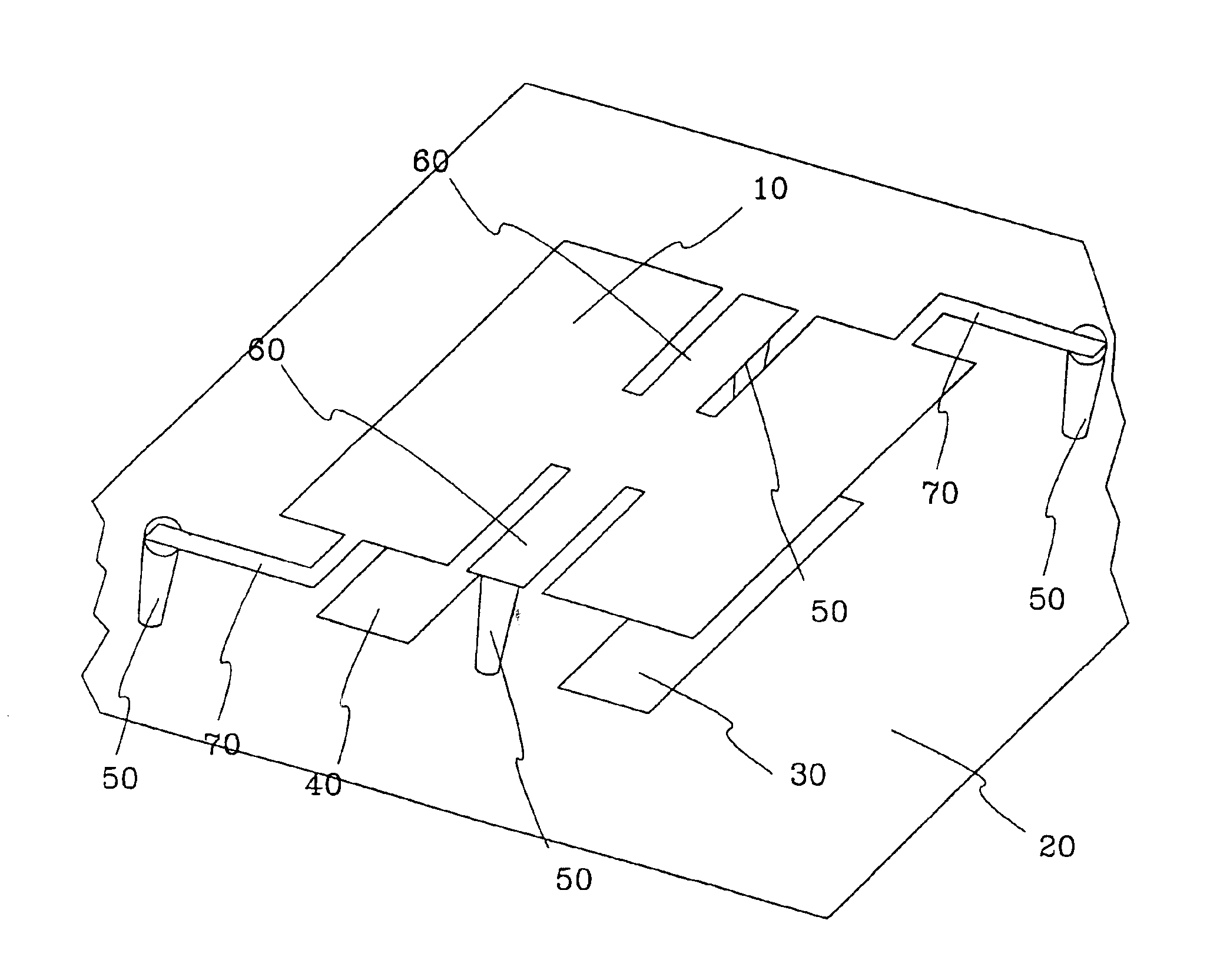
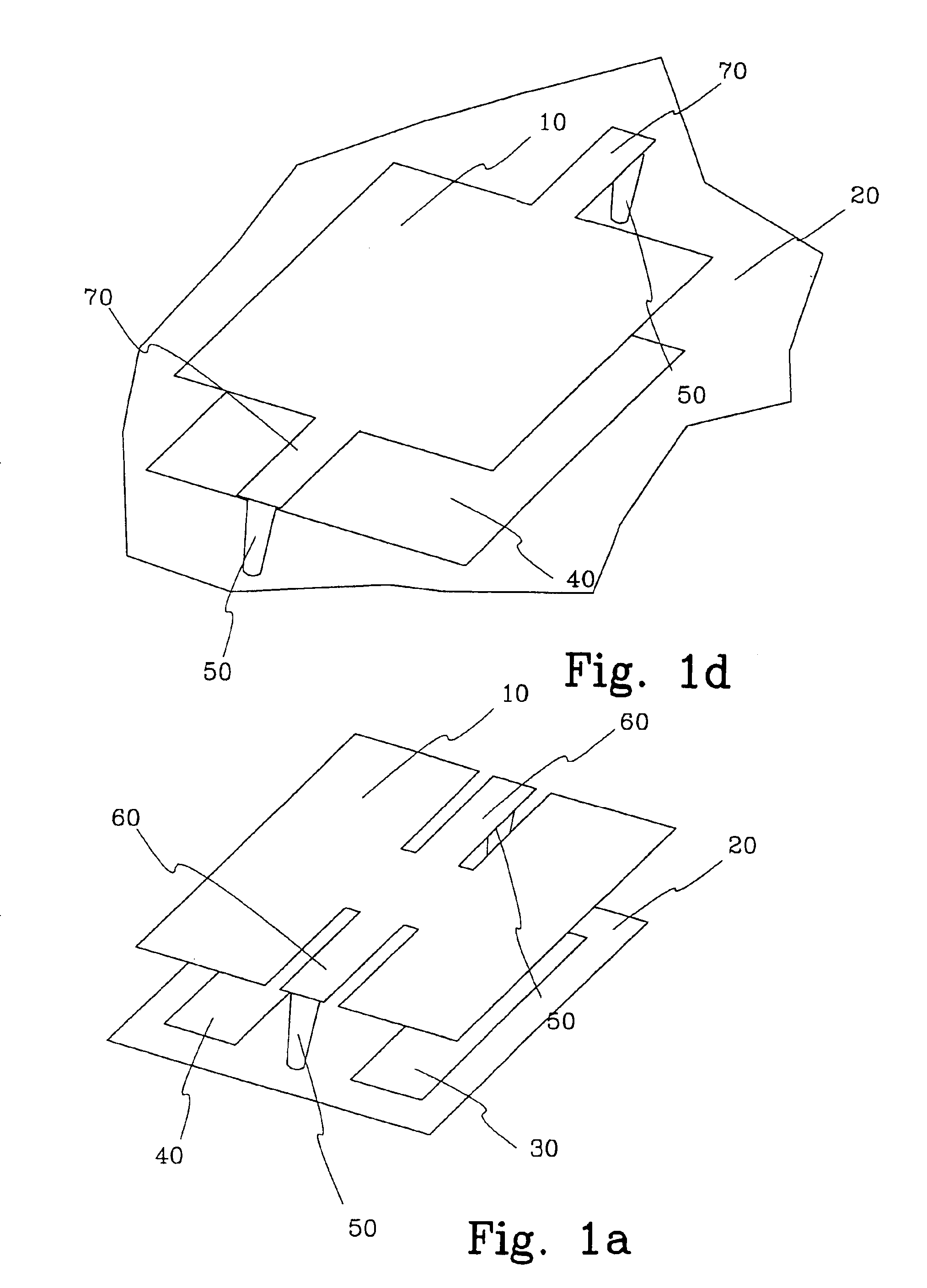
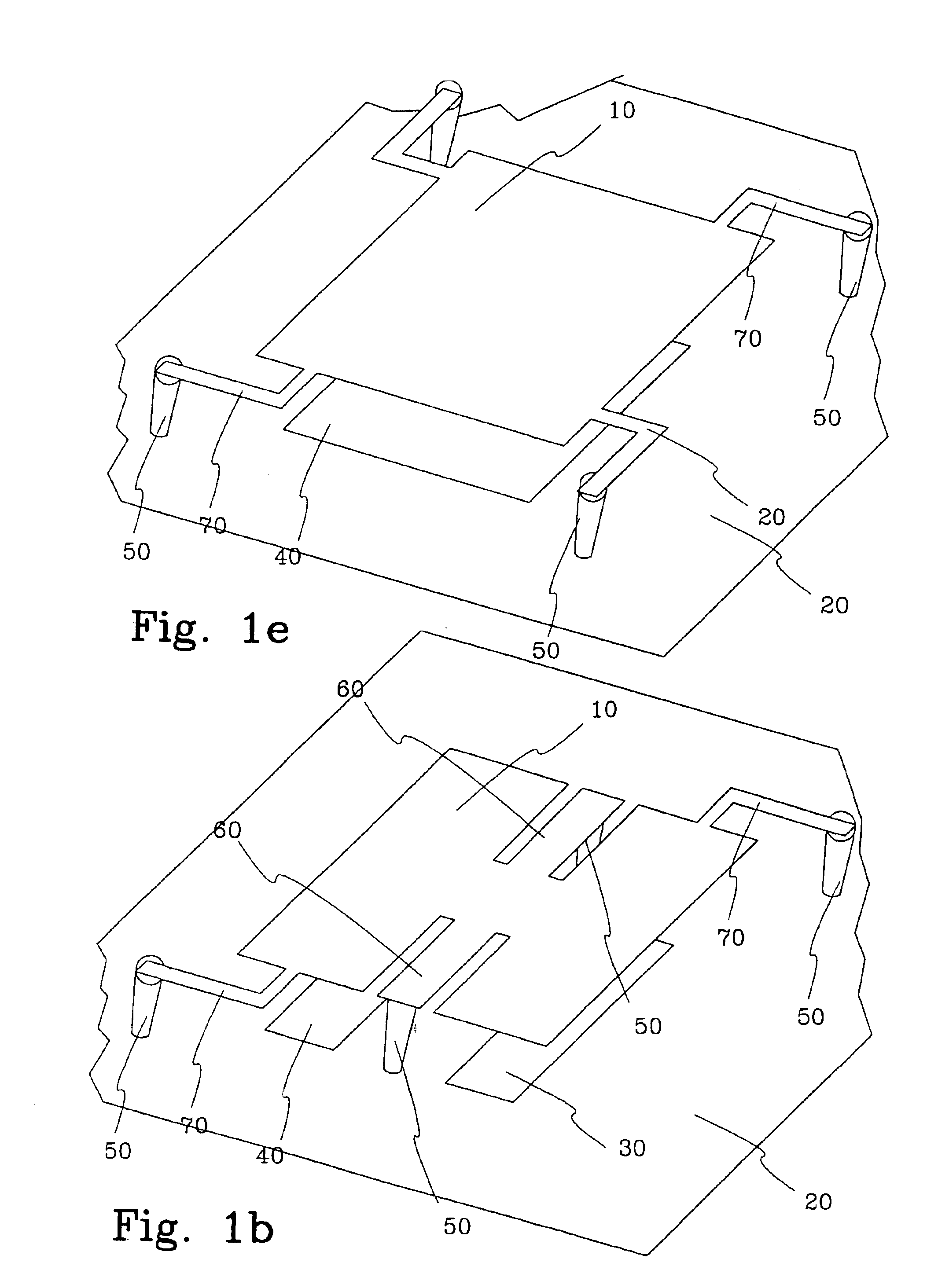
[0080]FIG. 1a shows a first embodiment of a movable micro-element, for example a micro mechanical element, with reduced imprinting effect according to the invention. Said movable micro-element may for example be a mirror in a Spatial Light Modulator (SLM). Said mirror may be operated in an analog mode to selectively steer the degree of deflection of said mirror element being a function of an electrical input or digital mode representing an ON and OFF state of the mirror element defined by maximum deflection and non deflection. The deflection of the mirror element may be generally linear or nonlinear, as a function of the input signal, depending on how said mirror (movable micro-element) is being mechanically affected.

[0081]In this embodiment the movable micro-element 10 is a generally rectangular reflective element supported along one its mid sections by a pair of torsion hinges 60. The reflective element may have any form for example polygonal, circular or elliptical. Said hinges d...


PUM


Abstract

The present invention relates to a movable micro-element with reduced imprinting or hysteresis effect arranged spaced apart from a surface comprising at least one electrode. At least one restoring element is connected to said movable micro-element. An address electrode is arranged on said surface and capable to electrostatically attract said movable micro-element. Said address electrode is addressed to a first potential. Said movable micro-element is first set to a second potential defining a non addressed state and at a time period Δt before a predetermined pulsed signal is emitted said movable micro-element is switched from said second potential to a third potential defining an addressed state. Said movable micro-element is kept in said addressed state for a time period of Δt+Δt′. The invention also relates to a Spatial Light Modulator (SLM), an apparatus for patterning a workpiece and a method of reducing an imprinting or hysteresis effect of a movable micro-element.

Description

TECHNICAL FIELD[0001]The present invention relates in general to techniques for reducing hysteresis or imprinting effects in mechanical elements, and in particular to a movable micro-element and a method for addressing the same.DESCRIPTION OF THE BACKGROUND ART[0002]Hysteresis or imprinting of mirror deflection amplitude in Spatial Light Modulators (SLM), which leads to a shift in a required address voltage for a preferred mirror deflection, is a problem since it reduces the accuracy of the mirror deflection. This shift depends on an amount of time that the mirror has been deflected, an amplitude of the deflection and a time that the mirror has had to relax after said deflection. The time constants for these phenomena are in the region of minutes / hours making it virtually impossible to predict and compensate the required address voltages for an arbitrary pattern in a mask writer or a direct writer using a state of the art SLM technology.[0003]A problem with a compensation for the im...

Claims


Application Information

Patent Timeline
Patent Type & Authority Patents(United States)
IPC IPC(8): G02B26/08
CPCG02B26/0841
Inventor LJUNGBLAD, ULRICLAKNER, HUBERT KARLDURR, PETER
Owner MICRONIC LASER SYST AB
Why Eureka
Try Eureka